


")

The device described here makes it possible to simultaneously stabilize the temperature and humidity of the air in the room. Unlike the majority of similar stabilizers that use the principle of resistance measurement hygroscopic material, in the present embodiment is applied psychrometric method of control when lowering the temperature sensor is greater than the intense evaporation from its surface. This allowed to simplify the design sensor and to improve the reliability of its work.
However, it should be noted that the installation of the stabilized humidity needs be made on a psychrometric table, which is not very convenient.
Schematic diagram of the stabilizer of temperature and humidity is shown in figure. Actually it consists of two thermostats. One of them is picked at the comparator DA1 and functions of the thermosensitive element runs dry the thermistor R3. The output of this regulator (connector XS1) connected heater power of about 1 kW, constant the temperature in the room. The second controller has a comparator DA2, which is connected to the "wet" thermistor R8. Temperature, and hence resistance continually moist resistor depend on the air humidity in the room. The output of this regulator (connector XS2) can be connected the moisturizing device - evaporator or the pump motor spray water through injectors.
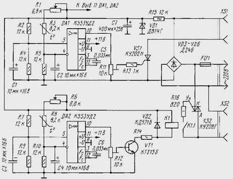
First the thermostat operates as follows. When the temperature of the air, and hence, the thermistor R3 is below the value set by the variable resistor R1, the voltage on the inverting input (pin. 4) of the comparator DA1 less than noninverting (pin. 5). In this case, the voltage at circuit output DA1 (vyv. 10) close to the voltage of power (about 11 In), SCR VS1 and open the heating device is connected to a power source. When the temperature will rise to a desired level, the resistance thermistor R3 is reduced, the voltage at inverting input circuit DA1 will increase, and the output will drop to virtually zero. As a result of SCR VS1 is closed and the circuit of heater is broken. At lower temperatures the process will be repeated.
Operation of the humidity controller on the chip DA2 is virtually no different from operation of the thermostat, but instead of SCR to the output of the comparator is connected the VT1 transistor that controls the triac VS2 via relay K1.
The temperature of the thermistor R8 humidity controller depends not only on temperature, and humidity. At low humidity the speed the evaporation of water from his constantly wetted surface is increased, as a result it is cooled and the resistance of the thermistor R8 increases. In this case the voltage on the inverting input of the comparator DA2 will be low, and its output - high. As a result, the VT1 transistor opens, the relay K1 will work and his contacts K1.1 will close. Triac VS2 will also open and connected to the connector XS2 the humidifier will receive the supply voltage. But as soon as the humidity will rise to the required level, the evaporation of water from the surface of the resistor R8 will decrease and its resistance will decrease. Triac VS2 is closed and power supply connector XS2 will stop.
All used in the stabilizer elements are widely known and available. Thermistors MMT-4 with a negative TCR can be replaced by other impedance 2…20 ohms, but the resistance ratio of R1:R3:R5 and R6:R8:R10 must be maintained. SCR CON can be replaced by COOL, diodes VD3-VD6 any powerful for a voltage exceeding 300 V. Fuse FU1 is chosen based on power devices attached to the connectors XS1и XS2. Relay K1 - RES-15 passport RS4.591.003 can be replaced with any other trip current not exceeding 10 mA and the winding resistance to 1000 Ohms. When using the relay with a small resistance the winding in the chain of supply should include a current limiting resistor R14 resistance of several hundred Ohms. All elements, except VS1, VS2, R1, R6, R16, FU1 and VD3-VD6, installed on Board of one-sided glass Micarta. SCR, triac and diode VD3-VD6 placed on a small the heat sinks.
In the described device uses a transformerless, so all conductive circuit must be well insulated. When you configure a device you must use low-voltage stabilized power sources.
To the body of the resistor R8 tie a strip of material with good capillary properties, the other end of which is lowered into the water. It is important that the body thermistor constantly specialsa. The adjustment device is to install threshold of SCR VS1 and relay K1. The engines of the resistors R1, R6 must be installed in the position corresponding to the greatest resistance. Resistors R11 and R12 is gradually transferred from the lower (on) position to a situation in which respectively open SCR VS1 and relay work K1. The device must be calibrated with a thermostat and handle variables resistors R1, R6 to provide temperature scales. During the calibration resistor R8 should not be wetted.
The desired room temperature is set by the resistor R1, and humidity - R6. To do this, use a psychrometric table, at which the temperature of dry thermometer temperature corresponds to the set resistor R1, and wet - the temperature set resistor R6.
It is important to note that due to galvanic coupling of the device with the network of filling stations capacity for wetting of the resistor R8 is only possible if you disconnect the network voltage.
This device is not very well resolved control SCR VS1 and triac VS2. The fact that the output current supply circuit R15VD1C7 - 16 mA - there may not be enough for the two op amps, the relay K1 and SCR VS1 (current-rectification - up to 100 mA at 20°C). In addition, the resistance of the resistor R16 provides a guaranteed inclusion of the triac VS2 only when the instantaneous value of voltage of 80 V, which causes marked interference radio. Therefore, the control circuit of the thyristors should be changed. Options schemes sites have their pulse enable repeatedly cited pages log.
Author: M. Kutsev, S. Volcano-Burla Altai territory