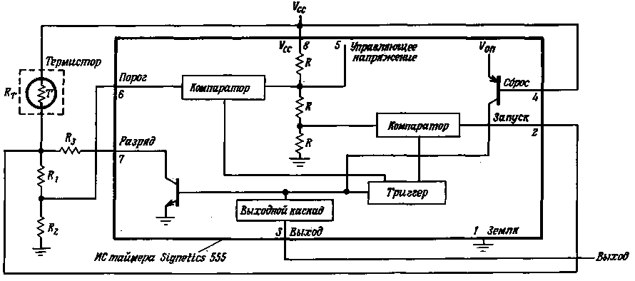
Although integral type timer 555 is primarily designed for chronologic schemes, but this is in conjunction with a thermistor having a negative T. C. S. can also be used to create low-cost and fairly universal scheme of solid-state thermostat.
Internal resistive divider of timer generates a reference voltage (1/3Vcc and 2/3Vcc) for both Comparators included in the timer. When the external voltage applied to the threshold input of the timer (pin 6) exceeds 2/3Vcc, the output of the corresponding comparator receives the impulse that transfers trigger. This turns on the discharge transistor, whereby the output of the amplification stage is a signal of low level.

(click to enlarge)
In most cases (including this scheme) unlocking of the discharge transistor of the timer causes the voltage at the threshold input becomes less than 2/3Vcc. If the voltage at the input trigger pulse (pin 2) drops below 1/3Vcc, the second comparator generates a pulse which returns the trigger to its initial state, the discharge transistor turns off and the output voltage of the amplifier circuit becomes the same high level.
Such action schema timer makes it convenient for the purposes of temperature control, in particular, electronic thermostats, inside which the temperature should remain virtually constant regardless of changes in ambient temperature within certain limits. With increasing temperature will increase (proportional to s), the voltage at the threshold input, until it reaches 2/3 Vcc. Then the state of the output stage timer will change and this will signal to turn on the cooling unit or simply to disconnect the existing thermostat heater. Then the temperature starts to fall, and when the voltage at the input of the trigger pulse reaches 1/3Vcc, the output stage will return to its original state, which will serve as a signal to turn off the cooling unit or switching.
In the schema of the thermostat shown in the figure, a voltage divider consisting of a thermistor and resistors produces a voltage directly proportional to temperature. When the temperature increases (high voltage level at the output of the timer, the discharge transistor is off), the voltage at the threshold input is determined by the division ratio R1/(R+ +R1+R2) and increases with the decrease of RT.
When RT is equal to the thermistor resistance Rтн at the upper allowable temperature difference, the dividing ratio, requiring that the voltage at the threshold input was equal to 2/3 Vcc must be equal to

After the voltage at the threshold input (the input of the first comparator reaches a specified level, the discharge transistor turns on, which is equivalent to the inclusion of R3 in parallel with R1+R2.
When the temperature drops, the value of R increases, and the voltage is now divided between RT and [R3II(R1+R2)]. When RT is equal to the thermistor resistance Rтc at the bottom point of the allowable temperature difference, the divider should give the input trigger pulse voltage of 1/3 Vcc. The division ratio should be

Thus, the voltage levels on the outputs of the divider consisting of the thermistor and resistors vary in different ways depending on whether the thermostat is in that part of its operating cycle, when the temperature increases, or when it decreases. This distinction is necessary to enter for the reason that the resistance of the thermistor varies with temperature quasiexponential the law, and even in a narrow temperature range it can change two or three times, i.e., the resistance of the thermistor Rтc at the bottom of the temperature range can be several times greater than its resistance Rтн the top of the temperature range.
If in this scheme we use a standard thermistor, for which the dependence of resistance on temperature is known, the calculation scheme is quite simple. When Rтс more Rтн in two or more times, it is possible to put R2=Rтс and K=Rтс/Rтн (constant coefficient). So in the divider proper relationship between the resistances, you need

But if Rтс/Rтн<2, then we must assume R1=0 and R2=2RТн, so

In all these formulas, it is assumed that the inputs of the Comparators do not load the voltage divider.
To the limits of temperature to which the thermostat is set, adhered to accurately, it is necessary to dissipate the thermistor as less electrical power. The self-heating of the thermistor can be minimized by forcing the IC timer to work at the lowest allowable supply voltage of -5 V. However, with a high top temperature regulation when the thermistor resistance can be quite small (a few hundred Ohms), this method may not produce the desired results. On the other hand, at very low temperatures regulation of permissible resistance of the divider should be selected based on the values of input resistance of the comparator.
To prevent false alarms from interference and crosstalk, it is necessary shall be shorted inputs of the comparator tanks. This is particularly important when high resistance of the divider, there are significant obstacles or thermistor is connected to the circuit by means of conductors of great length.
Author: De Cold; Publication: N. Bolshakov, rf.atnn.ru


