The need for measuring temperature due to by many circumstances. In everyday life, for example, the need for rapid measure the temperature of the human body or water, for bathing the child, the temperature inside or outside, in a greenhouse or Conservatory, in the basement, if there are vegetables, in the chamber of the refrigerator or freezer, the water in the aquarium and many other objects.
To household thermometers typically have such requirements, measurement accuracy is not less than 0.5 s in the temperature interval from -50 to +100 °C (when measuring the temperature of the human body - not better than 0.1...0.2 °C), compact size, efficiency, autonomy power, small thermal inertia and hygienic harmlessness. Described here is relatively simple digital thermometer mainly to meet these requirements.
The sensor element temperature of the device sensor, the principle of which is based on the property of some materials to change their electrical resistance when changing temperature. Temperature sensors may be different. In industry, for example, often use solid metal (copper or platinum) the thermocouples.
For household appliances are best suited semiconductor small thermistors MMT, CMT, ST1, ST3, TR-4,. MMT-4, which compared to metal converters significantly less teploenergiya, are almost ten times higher temperature coefficient of resistance (TCR), a higher electrical resistance, lets completely disregard the resistance of the wires that connect the sensor with the device. Best features miniature teardrop-shaped vitrified thermistor TR-4 reduced TKS. He has the size HH,5 mm; wire length 80 mm made of wire with a low thermal conductivity. His weight-0.3 G.
The main electrical characteristics of the thermistor TR-4: nominal impedance - 1 kω ± 2% at temperature +25 °C, TKS - about 2 %/°C operating temperature range -60...+200 "With, the time constant is 3 s.

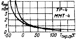
The disadvantage of semiconductor thermistors - the nonlinearity the dependence of resistance on temperature and the large variation of characteristics, what is the main reason hindering their widespread use DM measure temperature. The graph illustrates the typical dependence resistance of semiconductor thermistors TR-4 and MMT-4 temperature. However, the corresponding circuit solutions linearization characteristics allow largely eliminate these shortcomings.
Main technical characteristics of the thermometer with the use of thermistor TR-4:
- The measured temperature interval, °C . . . -50...+100
Resolution, °C . . . 0,1
The error of measurement, °C,
at the edges of the working interval . . . ±0,5
in the middle part of the working interval, not worse . . . ±0,1...0,2
The voltage of the power supply . . . 9
Current consumption, mA . . . 1
Dimensions, mm . . . HH
Weight, g . . . 250
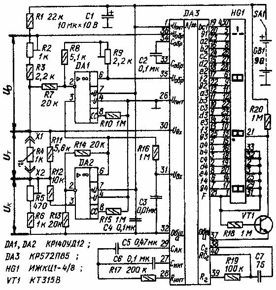
Schematic diagram of the thermometer shown in Fig. 1. The heart of the device is an integrating analog-to-digital Converter (ADC) DA3, the output of which is connected four-digit LCD indicator HG1. This element base has allowed to reduce power consumption and to provide a device of small dimensions and mass.

Fig. 1. Schematic diagram

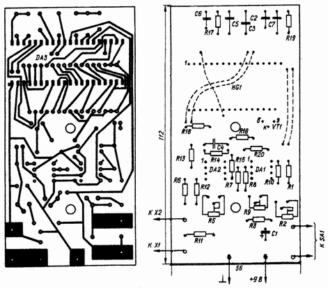
Fig. 2. The printed circuit Board
The measuring circuit of the device form dakotadome the resistor R1, resistors R2 and R3, forming the exemplary voltage Iobr, PTC resistor R4, the voltage of It, which changes according from the temperature compensating resistor, the function of which perform resistors R5, R6. To reduce error from self-warming thermistor the value dakotadome resistor R1 is selected such that the current measuring the circuit was equal to approximately 0.1 mA.
The device is applied to the direct measurement of thermal resistance method relationship - thermistor R4 and exemplary resistor (R2+R3) connected in series and through them, the same current flows. The fall the voltage produced on the thermistor, enter the input findings 30 and 31, and the voltage drop across the sample resistor that performs the function of the reference voltage source iobr, conclusions and 35 36 ADC DA3.
With this method of measurement the result of the conversion ADC does not depend on the current in the measuring circuit, and means that there is no the need for traditionally used high quality sources current and reference voltage, which largely influence the accuracy characteristics of the meter.
For the device operating in the temperature measurement mode, typical is the task of the compensation initial value of thermoprotei at zero temperature. For this resistance compensation resistor (R5+R6) is selected equal to the resistance of the thermistor R4 at zero temperature, and to compensate the sum of the values voltage It+IR received at the output 30 of the ADC, at its output 31 serves voltage equal to 2 IR, which forms the operational amplifier DA2 with a gain of K=(1+R14/R13)=2. Then, that with increasing temperature the resistance of the thermistor decreases, have the Uвх ADC = U+I - U-VH = 2Uк-(It+IR) = IR-It.
The linearization of the nonlinear dependence of the resistance temperature implement shunting the thermistor resistor R4 R11 - crudely, but accurately-introduction to the operation of the shelter DA1. But shunt resistor R11 is only partially straightens this nonlinearity, a few extending the operating temperature range.
The principle of exact linearization founded on change the ADC conversion factor depending on model, voltage Iobr. It changes due to feedback through the shelter DA1. When such a connection part of the input voltage Uвх defined by the ratio gain shelter In DA1=[1+(R8+R9)/R7], is added to the voltage iobr. The more increases the resistance of the thermistor at lower the temperature, the faster growing an exemplary voltage, and this leads the proportional decrease of the coefficient of ADC: Iobr=U+arr-U-arr=U0-B(IR-It), where U+arr-U-arr - voltage on the findings 36 and 35 ADC, respectively.
If you accept the price of division of LSB equal to 0.1, in the final form of the reading digital display НG1 determined the expression N=100Uвх/iobr=100(IR-It)/[(U0-B(IR-It)]=100(R5+R6-R4)/[(R2+R3)-(R5+R6-R4)]
Other elements of the thermometer, providing work ADC model. The transistor VT1, enabled by the inverter, is used to indication in digital display HG1 of the decimal point.
The parts of the apparatus are mounted on a printed circuit Board from foil fiberglass 1.5 mm thick. Chip DA3 is mounted with the printed conductors. Socket X1, X2 (from the connector RM) soldered directly to the printed Board sites. For mounting the switch SA1 is also provided a printing platform. Fixed resistors - C2-29V, trimmer - CP3-38A. Capacitors: C1 - C50-6, C3, and C7 - KU, C5 - K73-17, C2, and C6 - K73-24. Switch SA1 - PD9-2, battery power GB1 - "Corundum". Indicator IGCC-4/8 you can replace IZHTS-5.
The constructive design of the sensor is arbitrary. For example, in a plastic rod with a diameter of 5 and a length of 65-70 mm drill through the axial hole diameter of about 3 mm, and then in one of its ends a recess. The findings of the thermistor wear a thin insulating tube, the findings flow into the hole in the rod, install the thermistor in the hole and seal it with glue BOV-1 varnish CO. To the terminals soldered to the ends of the flexible two-wire cable and tight wear to the end of the rod opposite to the thermistor, cut thin-walled dural tube, which serves as the sensor arm. Cable length - 1.5 m.
Due to the significant scatter of the parameters of semiconductor the resistors in the device, enter three trimmer: R5-zero, R2 to set the scale and R9- linearization characteristics of the thermistor.
A simple adjustment of the thermometer is convenient to perform at three test temperatures: melt water (0 °C), body (36,6 °C) and boiling water (100 °C). In the first of these control points measure the water temperature in the ice, not ice water, the temperature which can be more than 1 °C. the second control point as model unit use a medical thermometer. Temperature boiling water is necessary to adjust the correction for atmospheric pressure. In Pyatigorsk, for example, located at an altitude of about 500 meters above sea level, water boils at a temperature of 92.5 °C.
Adjustment begin by placing the sensor in the melt water. A trimming resistor R5 set the indicator to zero reading. Then, by successive adjustment of the resistors R2 and R9 are making of the indicator corresponding to the temperature values in two the remaining control points. Further, the sensor will again interfere in the melt water and repeat measurement.
More accurate adjustment of the device can be performed industrial mercury thermometers with a scale interval of 0.2 °C.
Instead of the thermistor TR-4 in the sensor can be used other thermistors wider application, but with mandatory the adjustment of the resistance of some resistors of the device. So, when MMT-4 with a nominal impedance of 1.3 ohms resistor R11 should be reduced to 3.3 ohms, and when thermoresistor ST3-19 with a nominal impedance of 2.2 kOhm to 3 kOhm.
Modes of operation the ADC in use in the device thermistors TR-4 and MMT-4 shown in the table. If the limits of adjustment podstroechnye resistors, except R11 is not enough, then maybe have to pick up the resistors R3, R6, R8.
Author; V. Suetin, Pyatigorsk; Publication: www.cxem.net


