For weather observations typically use several devices, each of which measures one parameter. Recently went on sale portable electronic weather station foreign production, but they are pretty road. The author of the proposed paper is to develop an Amateur design similar device.
The weather station can measure three parameters: wind speed, temperature and atmospheric pressure. Information alternately (6 C) is displayed on four-digit semielemental led indicator. Four discharge continuously displays the current time: hours and minutes with a flashing decimal point.
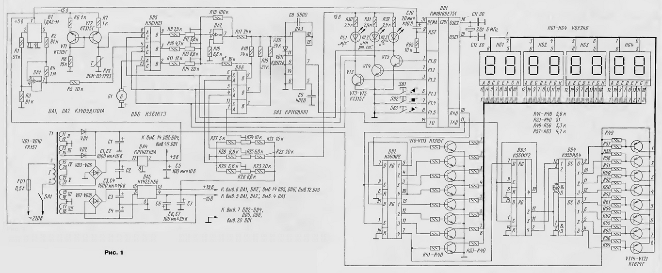
Diagram of the meteorological station is shown in Fig. 1.

(click to enlarge)
At the heart device is a microcontroller (single-chip microcomputer) CMO or CMO (DD1). Three-channel the multiplexer on the chip DD5, DD6 provides alternate connection one of the three sensors. Next, the signal goes to the amplifier DA2, and then the input of the Converter voltage-frequency DA3.
The configuration of the weather station may be different. For example, for two channels can to measure temperature (outside and in the house), and the third pressure
Information for the eight-digit display comes with controller on serial channel. This enables you to move the display (together with the registers and decoders DD2-DD4) to a considerable distance.
All control (setting the hours, minutes, enabling and disabling channels) are three buttons SB1-SB3. Button SB1 produce a selection of watches, minutes of the measurement channel, setting the hour or minute in the direction of decreasing or disable channel if the decimal points are flashing the selected parameter. Button SB3 correct watch in the direction of increase and turn the channel, if the lights are flashing decimal points of the selected parameter. Button SB2 performs the function "set/select". She works in trigger mode. If after selecting (one of the buttons SB1, SB3) press SB2, decimal points of the selected parameter blink, now it is possible to install option buttons SB1 and SB3.
The signals from the controller sequentially through 6, connect the sensor to another the input of the amplifier DA2. Synchronously with the selection of the sensor input changes DA3 a positive offset. This chip generates the output signal, the frequency which linearly depends on the input voltage.
Set the initial offset is necessary for all sensors, including the sensors, working from zero (wind speed sensor), so as to determine the sign temperature from the result of software and subtracted a constant 3000 (decimal), and the program processing result of the measurement is the same for all three channels. This makes the device more flexible: there is no rigid connection of the sensors to certain channels can be connected on two or three channels of sensors temperature, you can use any of the channels for homemade experimental sensors (humidity sensor, for example).
From the output of the chip DA3 pulse signal is input to the first timer/counter microcontroller. Wherein the second timer is programmed as clock divider and generates a signal 625 Hz for dynamic display (scan display) and the time interval is 1 second, during which the first timer counts the pulses from DA3. Further, from the received double-byte numbers in the first the timer is subtracted a constant 3000 (decimal), the absolute value of the result divided by 4, rounded up, is the decimal correction and cancellation trailing zeros.
The output of information is performed through the serial port in synchronous mode transmission (shift register). Channel information, changing every 6 s, displayed on the right four-digit display (HG3, HG4), and the hours and minutes - on the left (HG1,HG2).
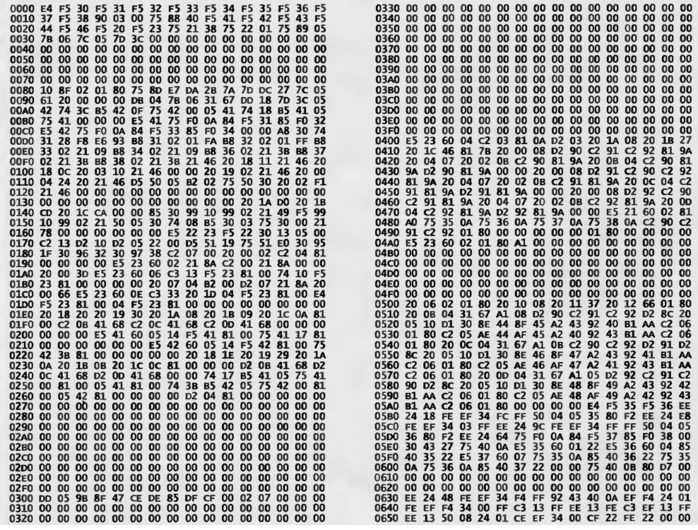
Capacitor C9 is customization, hence the special requirements for its accuracy and TKE. You can apply C-10. The capacitance of the capacitor C9 - 4020±40 pF. Capacitor S8 - tolerance of 5%. Dear chip CMI (ceramic case OPPSU) can be replaced with AT89S52 flash program memory. In the table given firmware controller DD1.

(click to enlarge)
Temperature sensor RK1 is copper resistor ENM-03-GR. It easily to produce and own: from copper wire of diameter 0.15 mm winding Bay 50 mm in diameter and, giving it an elongated shape, put into the casing of a ballpoint pens, preliminary Bay there sealant GED-1. If the device is supposed use only one sensor, no need for the exact fit his kg resistance: R = 50 ± 5 Ohms. Can be applied and integrated temperature sensor CAM, but since at the rated current is 1 mA and the zero voltage temperature on the sensor, equal to 2.73 In, enter the amplifier DA2 is in saturation, the initial the offset to the inverting input of DA2. You will need to install the resistor R' and unsolder R18.
Sensors absolute atmospheric pressure produce domestic firms: MIDA-DA-53 (MFA, Ulyanovsk), TGM-A, PAD-K01 (CJSC "icnt", Zelenograd). Sensors of foreign firms Bosch and Motorola are more expensive than domestic. For example, the MPX sensor OR company Motorola costs $ 15 and is inferior to our sensors main parameters: sensitivity and temperature dependence of This sensor you can buy at radio.
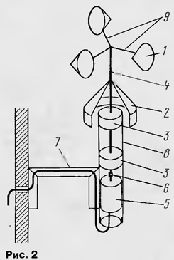
Possible sensor design wind speed is shown in Fig. 2.

Here: 1 - cone of galvanized iron (diameter at the base is 80 mm, height - 75 mm); 2 - protective screen made of galvanized iron (soldered to the axis); 3 - caprolan bearings; 4 - axis diameter of 8 mm stainless steel; 5 - Tacho G1 (the motor DPN-ZONES-19); 6 - coupling of rubber hose (better to use vacuum rubber); 7 - bracket; 8 - cylinder; 9 - steel spokes with a diameter of 4 and a length of 320 mm.
The establishment of the weather station is calibrated using industrial thermometers and barometers. Harder (for lack of a model unit) to calibrate the measuring of wind speed. When indicated in Fig. 2 sizes and used as a Tacho motor PDM-ZONES-19 experimentally obtained the following relation: U-740·n, where U is generated tachometer voltage in mV; n is the wind speed in meters per second.
Trimmer resistors R24-R26 adjust the offset, a, R12-R14 - toughness conversion.
The anemometer will be much more accurate and make it easier, if instead of Tacho use the optocoupler led-photodiode with rotating between them the obturator, the signal from the photodiode can be fed directly to the input microcontroller.
Table firmware
Author: S. Semiletov, Moscow


