The indicator of the field strength may be required when establishing a radio station or transmitter, if you need to determine the level of Radionova and find its source or for search and detection of hidden transmitters ("spy wireless microphones").

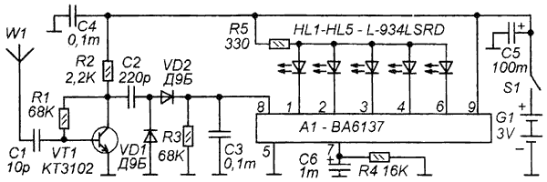
Feature indicator in the display intensity level on a five-level scale led. The indicator can control the field strength with frequency up to 1000 MHz. The frequency response of the indicator was not measured, because its function is not to measure the level of RF fields in absolute values, and to demonstrate the level and the change in this level in arbitrary units. However, if you have the necessary equipment, you can make the appropriate tables. Anyway, he confidently responds to the signal CB radio station operating in the range of 27 MHz and the cell phone signal operating at much higher frequencies. The radio frequency signal induced in the antenna W1, and is supplied to the amplifying cascade on VT1. Here a relatively low frequency transistor KT3102, probably using a transistor type KT368, CT you can improve the performance of the indicator on HF. The output amplification stage includes the detector with germanium diodes VD1 and VD2. The capacitor C3 is allocated a DC voltage whose magnitude is proportional to the intensity of the RF field. This voltage is measured by a scale indicator on poliambulatorio IC VA designed to operate at the level indicators. The field strength level is evaluated by a linear scale of five LEDs HL1-HL5.
The indicator is powered by the source of the two series-connected galvanic cells. Role the body plays a plastic holder for toothbrush In it are two batteries (one by one) and details of the indicator. Into the drilled holes glued the LEDs that form a linear scale. The findings of the LEDs and serve as anchor points for mounting the chip A1. The role of the antenna plays a foldable telescopic antenna (with swivel joint) radio or audio players. The hinge is fixed to the side of the case so that in the folded position of the antenna is parallel to the body. For her work unfold 180 degrees (or other angle) and pull to the desired length. The sensitivity can be adjusted by changing the length of the antenna.
When adjusting the transmitter indicator feature at a certain distance from its antenna, the value of which depends on the power and changing its radiation power estimate when the led scale. If necessary, remove the indicator or closer to the antenna of the transmitter. The indicator is useful for establishing a transmitter power not exceeding 0.5 W, otherwise it is too sensitive even with folded antenna and it has far to carry. In that case, if you need to indicate significant radiation power, can include a switch that turns off power UHF transistor VT1. Instead of the antenna you can connect surround the coil with a diameter of about 100 mm from 3 to 4 turns of thick winding wires. One end of the coil W1 is connected instead, and the second for a total of minus power. It is not excluded and exchangeable tunable circuits, on different frequency areas (get wavemeter).
According to the magazine crystal set kit.
Publication: www.cxem.net


