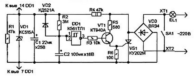
Sometimes you want light in the room was burning for some time after switched off by the switch. During this time you can safely leave room, then the lights go out. In Amateur literature described such devices, for example, in [1], but they contain additional (to the already the existing switch) button, which creates some inconvenience when use. In addition, in the device of [1] a Electromechanical relay the resistance of the winding which must match the power of the lighting lamps.
In the proposed device, no additional switching elements, in addition to the existing switch is not used. The device is connected in parallel the contacts of the switch SA1 via terminals 1 and HT.

When you open contacts SA1 voltage is supplied to the circuit through the light bulb EL1, is rectified by the bridge rectifier and VD3 is supplied to the electrodes (anode and cathode) thyristor VS1. and also on the parametric voltage regulator R4-VD1. The capacitor C2 through the resistor R2 is charging almost until the voltage on the Zener diode VD1. which corresponds to the logic level "1". served on the inputs of the Schmitt trigger DD1. At the output (pin 3) Schmitt trigger a logical "0" and the transistor VT1 is closed. The thyristor VS1 is also closed. Through the lamp EL1 current flows. determined mainly by the resistance of the resistor R4 (about 5 mA).
This current does not cause the illumination of the lamp. In this state the device can be arbitrarily long.
With the closure of the contacts of the switch SA1 switches lighting, and the voltage between the anode and cathode of the thyristor drops to zero. Capacitor C1 discharges through the resistor R1. and the capacitor C2 through the diode VD2 and the resistor R1. The time constant the purpose of the discharge is approximately 5 s. In this state, the device can also to be a long time.
When opened SA1 capacitor C1 quickly (within tenths seconds) is charged up to the voltage stabilization VD1, and C2 is charged through the resistor R2 is much slower, so that the output DD1 is set to "G which leads to the opening of the VT1 transistor and thyristor VS1. Thus the lamp EL1 continues to Shine.
The opening of the thyristor occurs not at the beginning of the next half cycle mains and 1...2 MS later, when the current of the control electrode exceeds the threshold value. The voltage across the lamp below voltage (170...180), and the voltage between the anode and the cathode of thyristor has the SCORM pulses formed part of the sine wave. This voltage enough to power circuits DD1 and the open state transistor VT1. It should be noted that the opening of the thyristor VS1 delayed relative to the beginning of halftime is a prerequisite for the job device.
After a time determined by the time constant circuit C2-R2, the voltage on C2 reaches the switching threshold DD1, the VT1 transistor and the thyristor VS1 is closed. For these in the diagram the values of R2 and C2, it occurs through 70., Uh, 80 p.
In the device used readily available parts. As the thyristor VS1 can take UK(L), KUK(L, M, N) and T, T, T, T. Transistor VT1 - CT. CT. CT. CT...CT. CT. CT with any letters. Bridge rectifier can be with the index and BR numbers, large indicated in the diagram (the first number represents the allowable current in amperes, and the second voltage in hundreds of volts). You can also use domestic rectifier bridge types KTS405 or CC (with the letters A... G). Thyristor and rectifier, in principle, must be rated for the current. more the rated current of the lighting lamp EL1 (when the lamp power 200 W valid the current and the thyristor bridge - 1 (A). When mounting the rectifier device bridge and thyristor are mounted on the radiator, if the lamp power exceeds 300 W.
To change the delay time turn-off are selected C2 and R2. If you increase the capacitance of the capacitor C1 up to 50... 100 UF. it is possible to achieve the flashing effect lamp EL1 before shutdown. This will be a kind of warning of soon turning off lights. The number of flashes and their frequency depend on the capacitor C2.
Literature
Author: A. A. Evseev, Tula


