In Amateur radio magazines described various designs of "running lights", but usually they have few lighting effects, and the maximum is eight. Offer the device produces a 128 effects that can be selected as desired, and the same effects automatically, one after the other.
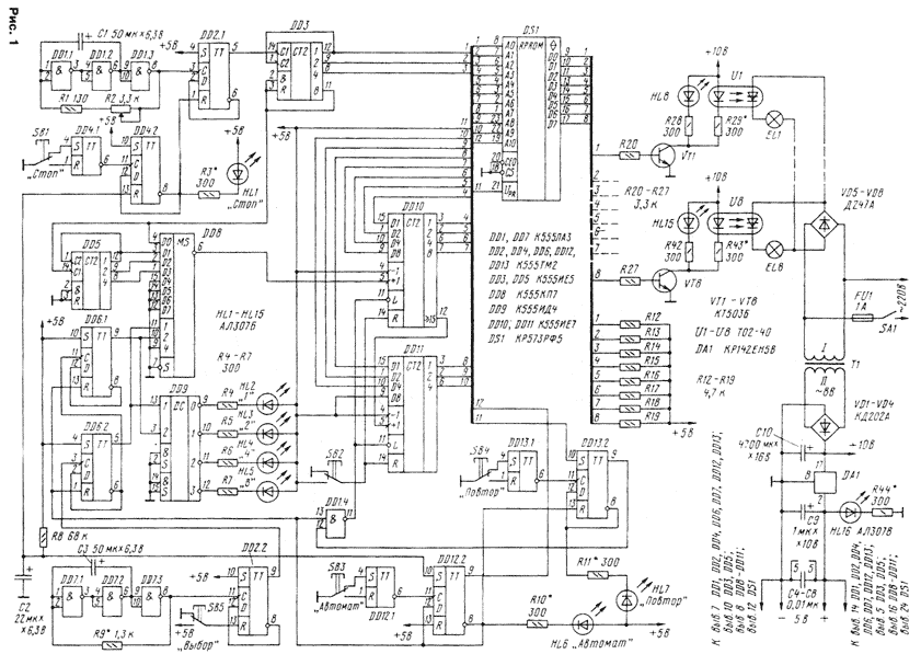
Diagram of the device shown in Fig. 1.

(click to enlarge)
On the elements DD1.1-DD1.3 assembled sets generator, the frequency of which, and therefore the switching speed of the tubes, can adjusting resistor R2. With the generator output signal is input to trigger DD2.1, performs the function of a divider by two. With its output signal twice the lower frequency is input to the DD3 counter, the outputs of which are connected to the younger bits of the address input of the ROM DS1. Eight States DD3 counter provide a sequence of inclusions of lamps, forming a single effect, for example, "running fire". The number of repetitions of these effects is determined the counter state on the triggers DD6.1, DD6.2, it can be 1, 2, or 4 8. The change effects are produced by counters DD10 and DD11 - only effects 128. As only the DD3 counter will count up to eight (fulfills one effect), it will happen reset to the zero state. Simultaneously, the counter DD10 increases your status per unit output of multiplexer DD8, and effect change. So it will be to happen, until all 128 effects, and then all again, starting with the first.
Auto mode sets the trigger DD12. After the voltage of the supply chain R8C2 sets the trigger DD12.2 in one state, the led is switched HL6 "Automatic". With direct access log. 1 is fed to the MSB of the address login ROM, which forms a switching cycle effects one after the other. With inverted output of the trigger DD12.2 log. 0 switches the triggers DD6 and DD13 in zero state. In turn the log. 0 from the outputs of the trigger DD6 goes on the address inputs of multiplexer DD8 and decoder DD9, the led is switched HL2 "1", indicating that each effect will be repeated once.
When you click SB3 "Automatic" trigger DD12.2 switches from single to zero conditions, HL6 led goes out, the log.About with direct access DD12.2 arrives on ROM, effects change. Log.1 with inverted output DD12.2 enables the trigger circuits DD6 and DD13. When you click SB4 trigger DD13.2 switches, including HL7 led "snooze". Log.1 with its direct output goes to the element DD1.4. Log.About from the output of the element DD1.4 translates counters DD10, DD11 in the parallel recording with their outputs. In this case, favourite the effect persists until a new button is pressed SB4 "snooze".
If you click SB5 "Choice", the trigger DD2.2 switches in counting mode. With multivibrator elements DD7.1-DD7.3 signal is supplied to the counter performed on the triggers circuit DD6. From the meter the binary code goes on the address inputs of multiplexer DD8 and decoder DD9, which determine the number repetitions of the same effect. For example, when the binary code 10 on the chip inputs DD8 and DD9 on the first digit decoder DD9 appears log.Oh, is included led HL3 "2", indicating that the effect will be repeated twice. At the same time code 10 on the address inputs of the multiplexer DD8 includes the first channel.
Counter DD5 is for counting repetitions of effects. When you reset the count DD3 the same signal is fed to the input C1 of the counter DD5. It will happen the switching to state 1, but the counter DD10 does not switch, because the input +1 multiplexer connected DD8 to the output 1 of the counter DD5. After the second reset DD3 counter DD5 switches to state 2 and switches the counter DD10. Each the effect will be repeated twice. When powering LEDs or HL4 HL5 the multiplexer will pass the signal from outputs 2 or 4 meter and DD5, accordingly, the effect is repeated four or eight times.
Button SB2 is designed to reset the counters, DD10, DD11. Button SB1 is used to stop switching of lamps. When pressed, the trigger DD4.2 switches from a zero to one state. Log. 0 inverted output is input to the R trigger DD2.1, lock; turn the led light HL1 "Stop". To enable "running lights", again press the button SB1 "Stop"
From the outputs of the ROM DS1 signals fed to the amplifiers, transistors VT1-VT8, which control the LEDs HL8-HL15 located on the front body panels, and LEDs with six. Instead of six will fit optosimistory, then a diode bridge VD5-VD8 is not required.
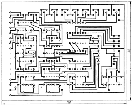
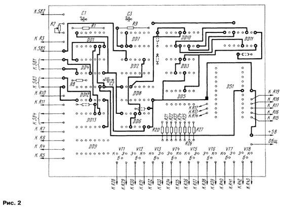
The main parts of the device are located on the PCB of bilateral fiberglass (Fig. 2).


Chip series K555 can be replaced by similar series KR1533 or K155. In the latter case, the inputs of circuits +5 V should be submitted through the resistors 1 to 10 kOhm (Fig. 2 they depicted by the dashed line). Transistors VT1-VT8 - any structure n-p-n medium power. Button SB1-SB5 - P2K, KM1-1 or other.
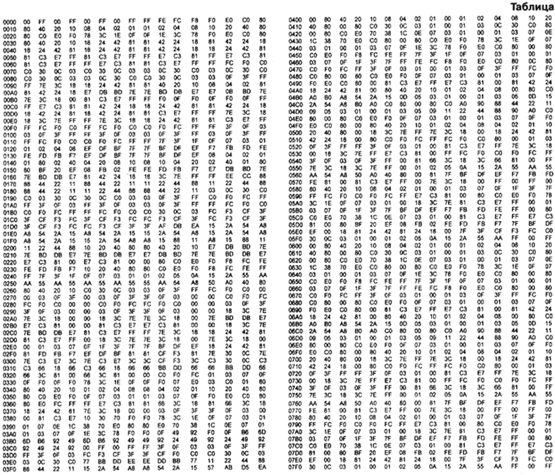
Codes in ROM DS1 shown in the table.

(click to enlarge)
Establishment slots is the selection of resistors LEDs with six full opening.
All connected to the chip contacts of the buttons SB1-SB5 desirable be connected via the resistors 5...10 kOhm to circuits +5 V.
Authors: A. Sinchenko, V. Yakushenko, Ozersk-10 Chelyabinsk region


