When disconnecting the mains voltage, say, in the country, often use compact and low-power fluorescent light (LDS) powered by the battery or battery cell. Offer Converter allows you to adjust the brightness of the lamp and install it like this, so battery power is consumed more efficiently.
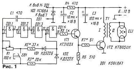
The Converter consists of a master oscillator and a single amplifier power (Fig. 1).

The generator is made on the elements DD1.1 - DD1.3 according to the scheme proposed in the book by S. A. Biryukova "Digital devices in MOS integrated chips" (M.: Radio and communication, 1990). This generator allows you to change duty cycle (i.e. the ratio of the repetition period of pulses to their duration) variable resistor R1, which determines the brightness of the LDS. To the generator connected buffer element DD1.4.
The signal from DD1.4 is supplied to the power amplifier, transistors VT1, VT2. Load booster - LDS (EL1) connected via step-up transformer T1. It is permissible to connect the lamp with closed conclusions of the filaments (shown on the diagram) and normally open. In other words, the integrity of the bulb filaments is not playing role.
It feeds the inverter from the DC source voltage 6... 12 V, able to give to the load current to a few amps (depending on the lamp power and set the brightness). Power to the chip is supplied through parametric stabilizer, which employs a ballast resistor R4 and the Zener diode VD3. At minimum supply voltage stabilizer virtually no works, but it does not affect the operation of the Converter.
Also indicated in the diagram, it is permissible to use transistors CTA, CTB, CTB (VT1), CTA, CTB (VT2), diodes series CD (VD1, VD2). Zener diode DA (VD3). Capacitor C1 - KT, KM, K10-17, the rest K50-16, K52-1, K53-1. Variable resistor - any design (for example, JS2, JS3), the constant - ALT-0,125. Lamp - with capacity from 4 to 20 watts.
The transformer is wound on a shell-magnetic core of ferrite outer 2000NM1 with a diameter of 30 mm. Winding of I contains 35 turns of wire sew-2 with a diameter of 0.45 mm, winding II - 1000 turns of PEV-2 0,16. The windings are divided in several layers of varnished cloth. To improve the reliability of the winding II should be divided into several layers, laying between them varnished cotton. Cups collect magnetic core with a gap 0.2 mm and tighten the screw and nut of a nonmagnetic material. With a few the worst results (the ratio of the brightness - current consumption) will work the transformer is formed on the yoke from the flyback transformer TV.
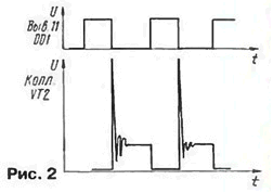
The establishment of Converter start with checking the master oscillator when disconnected the output stage of the amplifier. To pin 11 of the chip is connected the oscilloscope and observe the pulses shown in the upper graph, Fig. 2. Then set the slider of the variable resistor to the left according to the scheme position (resistance introduced). Measure the pulse duration and the period of the journey. The selection of resistor R3 to achieve a pulse duration of about 20 μs, and the selection of the resistor R2 is the follow-up period of approximately 50 microseconds. Moving after that, the engine from one extreme position to the other, convinced of changing the repetition period of pulses with constant duration.

Next, connect the output stage, the oscilloscope is connected to the collector of his transistor, and the power circuit is put an ammeter with a scale of 2-3 A. the Movement engine achieve "breakthrough" (a sharp increase in brightness) lamp and control the range of brightness and current consumption at different positions of the engine resistor. See the shape of the pulses at the collector of transistor VT2 - in Fig. 2 at the bottom of this form happened with inverter operation with lamp LB. Perhaps have precisely select the resistors R2, R7, and in some cases to install variable resistor value to achieve the required limits change the brightness and reasonable current consumption.
In the mode, minimum brightness, which corresponds, depending on the supply the voltage and wattage of the lamp current of 250...400 mA, the generator, and therefore, turning on the lamp, it is more convenient to implement by pressing the button SB1. Sometimes it is useful to try to change the polarity of the lamp and to check the reliability of her ignition in this mode.
To evaluate the efficiency of the Converter with different transistors, transformers, change modes, etc. Approximately 0.5 m from the lamp strengthen photodiode or photoresistor and connect ohmmeter. Measure the resistance at a burning lamp and a fixed current consumption Converter. Next spend replacement parts, resistor R1 sets still current and measure the resistance of the photocell. If it decreased, then the lamp brightness has increased, the result of the experiment is possible.
Author: V. Kobets, Feodosia, Ukraine


