


")

Author of published articles tried a large number of automatic switches in the utility room and opted for the design, which served him for over ten years. He developed the device, except simple schematics, different from the already known to our readers and more because it is when the door is closed the room and extinguished the light is de-energized condition.
Schematic diagram of the device shown in Fig. 1.
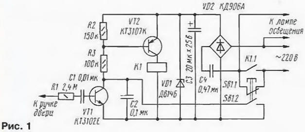
Push button switch SB1 placed on the jamb of the door. Inside the room door handle made of conductive material and are connected by wire with the output resistor R1. The diagram shows the position of the contacts of switch SB1 corresponds to the door is open. In this case, through the closed contacts SB1.1 power supply voltage is fed into the device, and lamp lighting. Transistors VT1. VT2 while closed, and the relay K1 is de-energized.
When the door closes outside the premises, the contacts of the switch SB1.1 break the supply circuit before closed contacts SB1.2, lighting the lamp goes out and the device is de-energized.
When closing the door from inside the room, the AC voltage induced on the human body, at the moment touch the inside handle through the resistor R1 and the capacitor C1 is supplied to the base of transistor VT1, which is opened, and the resistor R2 there is a voltage, which opens the transistor VT2. Relay K1 is activated, it the contacts K1.1 block contacts of the switch (SB-1).
In the complete closing of the door contacts SB1.1 open contacts SB1.2 closed, holding the transistor VT2 is in the open position and after releasing door handle.
The details of the circuit breaker is placed on the PCB size 40x50 mm, made of one-sided foil fiberglass with a thickness of 1 mm (Fig. 2).
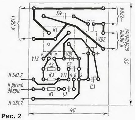
The fee is placed in a plastic box, mounted on the door. Used resistors MLT-0,125, capacitors km-6 (C2), K50-6 (C3) and K73-17 (With 1) working voltage 630 V and C4 - 250 V. Instead of VT1 can work any Malolos-tion corresponding transistor structure with the current transfer ratio base 150…200, and the place of the VT2 transistor is any transistor of the same series with the current transfer ratio base not less than 450…500.
Diode bridge KDA (VD2) replace diodes on KDB, CDV or small diode bridge another series (CCA, for example). You can also run from the bridge diodes series CD, CD, KD522 and others, but this will require changes picture of the PCB. Instead of the Zener diode DB suitable KSA.
Electromagnetic relays K1 - RES-10, passport RS4.524.308, RS4.524.311 or RS4.524.321. If the capacitance of the capacitor
C4 to increase from 0.47 to 0.68 µf, and as VD1 to use a Zener diode XA, the suit and relay RES-10 with passports RS 303, RS4.524.312, RS4 524.322.
As SB1 applied widespread push button switch II. In its absence, you can use any suitable switched voltage and current push button switch (e.g., KM2-1). The only condition replacement switches for the disconnection of contacts SB1.1 must occur before closing the contacts SB1.2.
The door handle is connected to the device by two twisted wires, preferably use the wires from the handset, a Single conductor connects the handle to the resistor R1, the second is connected to the negative output C3. In place of wire transfer from the door to the jamb do a loop.
When establishing a circuit breaker should be used with caution, since the unit of power is made by a transformerless circuit. First, even before connecting the switch SB1, include the device in the network, and touching hand output boards, intended for connection with the door handle, check, response of the relay K1. Then, by setting the switch in place, connect it with the door handle and the switch SB1 and make sure that when the door is open relay K1 is activated only in the moment when one hand touches the doorknob. If not, you need to select the capacitance of the capacitor C1. It is desirable that its value is minimal. After that, you close the door the outside. In this case, the lamp should be extinguished. If she continues to burn, it is necessary to reduce the capacitance of the capacitor C3.
In conclusion, check the operation of the device when closing the doors from the inside.
It remains to add that the interior door handle may be made from insulating material, but in this case, on its back surface need stick a plate of copper foil to which to solder the wire going to circuit breaker.
All circuit device electrically connected to the network, so when the Assembly and operation should avoid the touch of its elements, except left on the output circuit of the resistor R1. Should be carefully insulated end "shielding" wire wrapped with wire to the handle. To limit inrush current when you turn on sequentially with any of the findings of the diode bridge VD2 it is advisable to install the resistor 43…56 Ohm 0.5 watts.
Author: K. Kupriyanov, St. Petersburg