


")

Lighting a house number and street name in the countryside - not empty a whim but a basic necessity. In the dark the postman will be able faster to deliver the telegram, and online services - to help. Especially this is useful when the backlight lights up automatically at dusk and not requires human intervention. To make such a device may, perhaps, each, familiar with the basics of electrical engineering.
Electric circuit device automatic (controlled light) switch lights the room at home, working at the dimming of the working surface photoresistors are shown in Fig. 1.
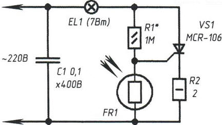
Fig. 1. Electric circuit device automatic (controlled light) switch lights the room of the house that is triggered when the dimming working the surface of the photoresistor
Incandescent lamp mounted inside a matte plastic casing plate the house number and the elements of the device in the wall of the house, in a closed and protected from moisture the body.
In natural lighting the lamp does not light. At dusk, when lighting drops, the bulb lights up, illuminating the number plate home.
The photo sensor is a photoresistor, which penetrates through the lens external the luminous flux. Photoresistor FR1 - brand RFT-01 used as of the image sensor in the controller of rotation of the turntable "Arcturus-004". Instead it may be possible to apply also the photoresistors mounted in the coupler EIA-1.
Under the illumination of the photoresistor (bright sunlight), its resistance drops to 12 ohms and shunt switch control electrode - cathode of the thyristor VS1. When this thyristor is closed and de-energizes the incandescent lamp EL1.
For such illumination is sufficiently low-power lamp 7 - 15 watts.
To use the device more powerful bulb is not because of the possibility of overheating and melting of the plastic cover plates.
With a lamp power of 7 W for backlight refrigerators, sewing machines and other household appliances, the device was operated in the fall in two days (with constant firing the lamp EL1), the temperature around the bulb is not climbed above 30°C, which is quite acceptable.
In low light the sensor, what happens in the dark, the resistance of the photoresistor large (over 1 MW). The current flowing through a current limiting resistor R1, it is sufficient to open the thyristor.
Establishment. To increase the photosensitivity of the node can be replaced by the permanent the resistor (R1* equivalent circuit as shown in Fig. 2, entering into the node adjustment. The possibility of changing the resistance R1 is achieved by increasing or the decrease in the current through R1 and the change of potential at the middle point of the divider voltage R1FR1. Because of this if you increase the current through R1 (reduced resistance) repeatedly increases the sensitivity to external site darkness. Now the lamp works faster when it is dark (includes backlight).
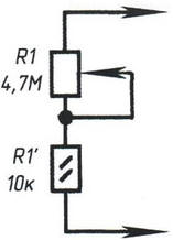
Fig. 2. The equivalent circuit of the resistor R1*
This decrease in current through resistor R1 (increase of resistance) will happen reverse - the lamp becomes more sensitive to outside light on and off illumination even at low impact on the working surface of the image sensor light stream. Variable resistor for adjusting the sensitivity threshold apply either (after adjustment by measuring its equivalent resistance, R1 replace constant).
To install it into the device requires minimum dimensions variable resistor. If you want to retain the ability to adjust, suitable multi-turn variable resistor SDR-BW or similar rigged resistor.
Phasing inclusion in the network 220 to the device are not principled.
About the details. The thyristor VS1 - type MCR-106-8 (marked MCR-106). It designation is shown not by chance, since the thyristor for this scheme, you can choose and another, guided by background material on the electrical characteristics thyristors and triacs company Motorola.
The capacitor C1 is type MBM or similar at a working voltage of 300 V.
With increasing power load is more than 60 watts, the thyristor must be installed on to the heat sink.
Issues of application and prospects. The electrical circuit shown in the figure, it is possible to assemble for use in other structures as simple photosensor. While taking into account the following points: the thyristor VS1 replace domestic triac COG. The constant resistor R2 from the circuit rule out instead, install the jumper. The resistor R1 is replaced by another with the power dissipation of 2 W and a resistance of 12 -18 ohms or an equivalent scheme (if need to adjust the sensitivity and threshold of the relay) with such same total resistance. Photoresistor FR1 is the same as in the basic scheme. When changing to a different type of resistor R1 will have to pick additionally in the other.
In the experiments has not done without incidents. So, managed to find the only normal working of triac out 6(!) copies of the notice, brand new and purchased in one party! The main "marriage" among these devices comes down to increased current leakage is visually noticeable as flicker the lamp even in the absence of a control signal on the control electrode. Like this the triac must be replaced, despite the "newness".
In some cases, if the bulb will burn continuously and does not respond to the change in resistance of the photoresistor, you will need to "flip" the triac, connecting it the other way around (the gate electrode does not change). Practical the explanation for this phenomenon is not, perhaps this is another surprise from thyristors COG.
Author: A. P.