More than four years I use fluorescent lamps with a homemade high frequency power supplies (electronic ballasts) on the basis of chips company International Rectifier. Lessons learned I want to share with radio Amateurs. The typical layout and design of ballast in sufficient detail described in the article A. Tarasova "high-Frequency power supply fluorescent lamp" ("Radio", 2003, № 5, p. 42), tell only about some of the features that the author is not paid, in my opinion, sufficient attention.
At the time of switching the unit to the network in the circuit L2C6 (see Fig. 1 in that article) oscillations, the amplitude of which is as a result of resonance can reach 1000 V. In the fluorescent lamp occurs cold discharge by ion bombing its filament lamp is warmed up and goes into normal operating mode. The ignition of the lamp in this case is instantaneous, but significantly (several times) reduces its service life. Therefore, such "cold" start is advisable to apply only where it is important to turn on the light without delay.
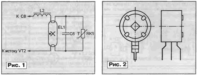
To eliminate the "cold" start-up and its implications, I recommend, as shown in Fig. 1, connected in parallel with capacitor C6 PTC (PTC-thermistor) RK1. The resistance of the PTC at the time the power is not enough, he bypasses capacitor, drastically reducing the factor of the circuit L2C6 and not allowing the voltage between the electrodes of the lamp to reach a value sufficient to cause cold discharge. The current flowing through the inductor L2, it heats up the filament lamp EL1 and the connection. The resistance of the latter with the heating increases significantly, the voltage between the electrodes of the lamp increases. 1...2 it ignites, gently moving into work mode.

The heating cables with necessary parameters in a quantity sufficient for eight electronic ballasts, can be made of the widespread of the PTC ST15-2-220 (Fig. 2) from the system degaussing TV ZUSTST. Dismantling plastic housing, remove the two "tablets". Diamond needle file to make each two nadela crosswise, as shown in Fig. 3, and break her in the nadpilov into four parts.

To the metallic surfaces thus produced of the PTC is very it is difficult to solder the pins. So I, as shown in Fig. 4, make in print Board 3 rectangular hole and clamp chip "tablets" 1 between the elastic the contacts 2 are soldered to printed conductors. By choosing the size of the chip can to achieve the desired length of heating lamps.
The capacitor C6 must be rated for a voltage less than 1000 V. Winding inductor L2 should have good interlayer insulation and be securely isolated from the magnetic circuit. Since the diode VD5 applied voltage a frequency of 30 to 40 kHz, low frequency 1N4007 better replaced by CDD, or BW95C another high frequency rectifier diode. Capacitor C7 can be set ceramic or film capacitance of 0.1. .0,33 UF. This capacity is quite enough, but the reliability of the unit will increase significantly. The IR2153 chip in need without any alterations, you can replace the already outdated IR2151 or IR2152.
Can't agree with the recommendation to apply in the high-frequency power supply MOSFETs IRF840. At the time I did in an attempt to increase reliability block made this mistake. It was later revealed that the main cause of overheating failure of transistors in such blocks is not greater the fall the voltage at the open channel of the transistor (through it flows a small current), and dynamic loss of energy to recharge a relatively large output capacitor of the transistor. This effect is masked by the fact that when properly configured circuit L2C6 its reactive component of the resistance of the partially compensates for capacitive part of the output resistance of the transistors. However, the compensation for violation failure of the lamp or as a result of breakage in its circuit almost inevitably leads to overheating of the transistors. Replacement transistor IRF840 less powerful, but more fast IRF710 whose internal capacity is much smaller, greatly increases the reliability.
A few words about the establishment of the unit. Equality of frequency of the master oscillator chip DA1 resonant frequency of the circuit L2C6 the easiest way to ensure not the change of the gap in the magnetic circuit of the inductor L2 and the selection customizados resistor R1. For this purpose it is convenient to temporarily replace a pair of sequentially United resistors: DC (10... 12 kω) and trimmers (4,7 10... kω). The criterion for the correct settings are reliable startup and steady burning lamp.
With the widespread fluorescent lamps with a length of 600 mm and a capacity of 18 to 20 watts I usually use the choke inductance is 1.9 mH and capacitors K-2 a 0.01 UF 1000V Optimum operating frequency of about 36 kHz.
Author: V. Chulkov, Moscow


