Fluorescent lamps daylight (LDS) are not only cost-effective, but also long service life, which, unfortunately, rarely is fully implemented. It is caused by a blown filament lamp or premature loss of its emission cathodes.
Already published a lot of tips "revival" of LDS, not suitable for use when turning on traditional schemes. Most of them boils down to the lamp power constant current increased, compared to nominal voltage. As a rule, it only gives short-term effect, flowed as a constant current causes the accelerated degradation lamps and very soon it fails completely. We talk about several circuits of the lamps, which can be installed with LDS blown filaments. Their common feature and that through burning lamp only flows an alternating current.
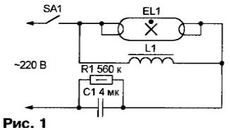
S. EREMENKO from Chisinau (Moldova) offers to remember a forgotten method of ignition LDS due to the resonance in the resonant circuit formed by the connected in parallel to the lamp inductor and "ballast" capacitor. In your device, scheme which is shown in Fig. 1, used available in any standard the lamp elements: the capacitor of 3.8...4 μf and the inductor OBI-40/220-EAP-U or similar.

While LDS is not lit, the quality factor of the oscillating circuit L1C1 is relatively large, and when closed the switch SA1, the voltage on the inductor L1 exceeds the network, reaching sufficient to cause gas discharge in LDS EL1 values. The outbreak of the lamp bypasses the throttle, reducing the factor of the circuit. Voltage reduced to necessary to sustain the discharge. In principle, the throttle after this is no longer needed and can be disabled. The audit showed that "short" (capacity of 15 to 20 watts), and "long" LDS with good emission cathodes lit securely and steadily burn.
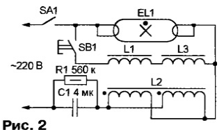
If the emission degraded in parallel LDS will have to include, as shown in Fig. 2, two connected in series inductor (L1 and L3) of the type specified above. In series with the capacitor C1 there is a choke L2. As inductance standard a single for it is too big, used winding the throttle UBE-40/220-runway-W windings which are connected parallel. Pre-closing switch SA1, light LDS touch button SB1. Once the lamp is lit, the button can be released. If extra button spam, chain chokes L1 and L3 can be left closed permanently or to provide for its short-term (0.1 .0.., 5) circuit relay with a simple timer.

Instead of two standard inductors L1 and L3 can be set on homemade the magnetic transformer TCA-70. On each of the magnetic core is wound with 500 turns of wire sew-2 0,51, and one of the two windings do with taps every 50 turns. Connecting windings in series, right the inductance is selected empirically, switching taps. Sometimes to to achieve reliable ignition LDS, the capacitance of the capacitor C1 is necessary to increase to 6 (for "short" lamps) and even up to 8 UF (for "long").
Applying a pre-owned standard chokes, it should be borne in mind that in they are frequent inter-turn short circuits. To distinguish faulty from serviceable by strong heating during operation. To measure power consumed by the lamp on LDS power should be by dividing the amount expended for them enough an extended interval of energy (this value is determined by conventional the meter) for the duration of this interval. Method voltmeter-ammeter due to the significant phase shift between current and voltage is correct .
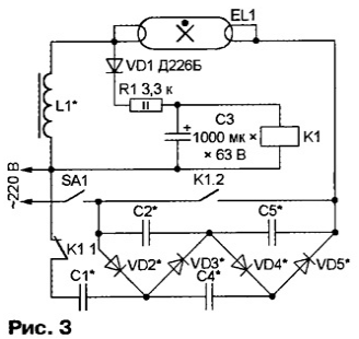
M. BYKOWSKI from Orel has developed a device start-up LDS, where necessary for lamp ignition voltage is acquired by the rectifier multiplying the voltage. After the occurrence of the discharge tube and off burning LDS supports the alternating current flowing through a conventional throttle. The device is assembled according to the scheme shown in Fig. 3, tested with the LDS power from 20 to 80 watts.

The types and values of items that are marked in the diagram by asterisks, for LDS of different capacities are given in the table.

After closing of the switch SA1, the current through the inductor L1 does not flow and the relay K1 remains de-energized. Through normally closed contacts K1.1 network voltage is supplied to the rectifier by multiplying the voltage (diodes VD2-VD5, capacitors C1, C2, C4, C5). As a result, the lamp EL1 applied sufficient to the occurrence of gas discharge high (1000 -1200..In) DC voltage. When the lamp EL1 lit and in its circuit drip the current in the positive half-cycles the voltage drop across the inductor L1 is charging the capacitor C3 through the diode VD1 and the resistor R1. After a few seconds (this delay allows the cathodes LDS to warm up due to the ion bombardment), the voltage on the capacitor becomes sufficient for the operation of the relay K1, and the contacts will eliminate the multiplier voltage of the supply circuit, LDS.
Relay K1 - RES execution RF4.519.021-00 with a winding resistance of 3500 Ohms and trip current of 14 mA. You can apply another trip current is not more than 30 mA and the maximum allowed voltage between open contacts 1,500 V. When replacing the relay should pick up the value and wattage of the resistor R1. Capacitor C3 - C50-24. It must be rated for a voltage of less fold voltage of the relay K1.
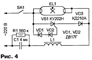
Their method of ignition of the LDS and A. shares DOGODILO from the city of Cherepovets. The basis taken the classic scheme, but in the proposed device (Fig. 4) a discharge in the lamp occurs due to the application thereto of a voltage almost equal to twice the amplitude network. As soon as the instantaneous voltage between the electrodes is not burning lamp EL1 exceeds (in the positive half-cycle) the total voltage stabilization diodes VD1 and VD2, will be open SCR VS1. As a result the capacitor C1 through the SCR, diode VD3 and the inductor L1 is charged to the amplitude value of mains voltage (220-1,41-310 In). The following negative halftime diode VD3 is closed, so SCR VS1 and Zener diodes VD1, VD2 in the work is not involved, recharging of the capacitor C1 does not occur. Thanks surviving the charge of the capacitor voltage between the electrodes of the LDS in this halftime reaches 620, which leads to the ignition of the lamp.

The voltage drop on a burning lamp (approximately 150) is no longer enough to opening Zener with a total voltage stabilization 180, so SCR VS1 no longer opens. The current through LDS, like when you turn according to the classical scheme, is limited by the circuit C1L1.
Two Zener DG you can replace an arbitrary number of other, bothering, to their total voltage stabilization was within 180...270 V. A chain of series-connected Zener diodes in extreme cases can to replace conventional resistor. However, the value it will have to pick up in a wide the interval, because the variance of the current inclusion even of the same type of triacs is very great. To guarantee long-term stable operation of the device in this case impossible.
As a substitute of SCR CON suitable CUA-COW, KWA-COD, CUI, CUI and others, suitable for direct current of not less than 0.5 A and can withstand in the closed state forward voltage 400 V. the Diode VD3 - anyone with a permissible reverse voltage of at least 700 V and a direct current of 0.5 A.


