The headline words, traditionally, from the first publication of this the theme is referred to as a device, comprising periodically on and off the lighting in the apartment or in the country, thereby simulating the presence of people. Despite some doubts about the effectiveness of such measures of protection against uninvited guests and the risk of fire is left unattended electrical appliances, the problem continues to excite many readers. Today we publish descriptions two machines "Evening light", developed by the authors of our journal.
E. ZUEV from S. Dentino Vladimir region considers the main drawback devices, published in [1, 2] that they include lighting one or two times a day at the same time regardless of the season. Optimal, he the view, the daily cycle of the machine in the winter time: in the morning for two hours the light is switched on, eight off, then six, and included eight off. Summer lighting appropriate to include daily two hours in the evening time. If the Windows of the protected areas are in the shadow of other buildings or vegetation, the "winter" cycle can be used all year.
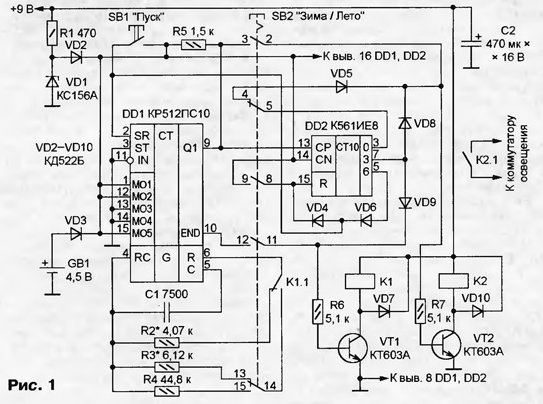
Diagram of the machine shown in Fig. 1.

If the push button switch SB2 is shown in the diagram position, the device is in "winter" mode. After applying power and pressing the button SB1 "start" the timer DD1 [3] starts counting time, and DD2 counter will be set to the state corresponding log. 1 conclusion 3. The VT2 transistor opens, the relay K2 will work and their contacts the lights are on.
As on all the other outputs of the counter DD2 - log. 0, the transistor VT1 will remain closed and the relay contacts To 1.1 is in the state shown in the diagram. In customizados circuit clock timer DD1 will be included resistor R2, selected so that the repetition period of the pulses at pin 9 DD1 - 4 hours after half of the period (2 h) instead of the log. 1 at pin 9 DD1 will log. 0. As a result, the counter DD2 will change and the log. 1 with its output 3 will move to pin 2, not shown in the diagram. Transistor VT2 is closed, the relay K2 will disconnect the contacts, the light will go out.
After 10 h after start of the log. 1, "moving" every 4 hours with one output counter DD2 on the other, will reach its pin 7. Transistor VT2 will again open, lighting is enabled. At the same time opens the transistor VT1 and work relay K1. Place customizados resistor R2 is R3, frequency the clock generator DD1 will decrease, resulting in the log. 0 will appear at pin 9 DD1 only after 6 h. At this point, the counter DD2 will change again and both transistor closes, turning off the light and restoring the old frequency generator. After another 8 h in the log. 1 appears at pin 5 of the counter DD2. Through the diodes VD4 and VD6 it goes to the inputs of the timer and counter in the source the state, after which the cycle will repeat.
In "summer" mode button SB2 fixed in a pressed state. DD2 counter not valid, since at its input R via one of the groups of the contacts button filed log. 1 banning the account. Other groups of contacts break the chain that links conclusion 3 DD2 with the base of transistor VT2, and connect it to the output 9 of the timer DD1. The signal from the output DD1 9 through the closed contacts of the button SB2 is supplied to the base transistor VT1. The last group of contacts replaces the resistor R3 in castorocauda circuit clock generator DDI resistor R4.
Joined after pressing the button SB1 lighting 2 hours off, as to log. 1 at pin 9 DD1 will change to the log. 0. Simultaneously appearing at pin 10 DD1 log. 1 will trigger the relay K1 switching castorocauda resistors. The oscillator frequency is reduced to such an extent that the new state change outputs timer DD1 will only happen through 22 h, after which the lighting will turn on and the cycle will repeat.
The machine is fed with a 9 V from any power supply that provides current load of at least 300 mA. Battery GB1 of three to four electrochemical cells backup. It ensures continuous operation of the circuits or accidental intentional disconnection of the main power source, preventing the violation cycle of operation of the device.
The establishment of the machine is reduced to the compilation of accurate resistors R2 - R4. Error perform this operation together with the inherent chip CRES instability frequency built-in generator leads to the fact that every day moments actuation of the automatic shift for a few minutes. From the point of view of approximation the observed pattern to the natural it is even useful. However, once in some days the machine has to restart. In "winter" mode button Start to press at 6 a.m., in "summer" - in 22 hours
Resistors R2-R4 is preferably used precision C2-29B, the capacitor C1 is mica C -11 -3. The remaining resistors - MLT, ALT, S2-23. Button SB1 - Pknb-1 without fixation, SB2 - P2K with fixation. All diodes can be series CD, KD521, KD522. Relay - RES-passport RF4 32.500.385-01. Transistors - CT, CT with any alphabetic indices.
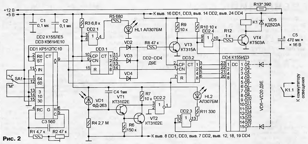
A. BUTOV from S. CORBA Yaroslavl region offers to assemble the machine "Evening light in the circuit shown in Fig. 2. The device does not require run strictly in a certain time, the cycle automatically begins with the onset of twilight and consists of 16 one-hour intervals. In each of these lighting can to be programmed on or off. In the early and mid hours the lights on a few minutes off, which increases the effect the presence of "owner". As each day twilight comes at different times, accordingly and the start of the work machine.

(click to enlarge)
The generator control pulses built on a chip DD1 CRES, as in the previous design. Its control inputs connected so that when the switch SA1 is set to "H", DD1 chip divides the frequency his clock on 7864320. The DD3 counter.1 divides the frequency of the output pulses DD1 another 16. So that the pulses at pin 14 DD3.1 appeared with a period 1 hour (3600 sec), the frequency of the clock generator chip DD1 should install equal 7864320-16/3600*34952 Hz. The switch SA1 in position "M" reduces the division ratio of the chip DD1 60 times, and the period following pulses at pin 14 DD3.1 - up to 1 min, which is convenient for setting and checking machine. If this is not necessary, the switch can be deleted.
Pulses with a period of 1 h to the input of the counter DD3.2, the outputs of which the connected decoder DD4. The outputs of the last one log. 0. The programme of work of the machine set installation of diodes VD6 - VD20. If the diode is there, in the new time interval at the input 8 of the element DD2.4 log. 0, the output log. 1, the transistor VT4 open. This will trigger the relay K1 and the light comes on. Otherwise (no diode, its circuit torn) input 8 DD2.4 - log. 1 and the lighting is off.
Diodes VD2 - VD4 and the transistor VT3 are used for short-extinguishing lamps. "Inside" each hour interval there are two period of time the length 3.75 min when none of the findings 11-13 counter DD3.1 no log. 1. In these intervals the transistor VT3 is closed, the input 9 DD2.4 - log. 1 and regardless of the logic level at the input 8, the lighting is off.
The synchronization of the machine with the time nightfall comes as follows. While the illumination of the photodiode VD1 is high, the transistors VT1 and VT2 open and log. 1 at the output of the element DD2.2 keeps the counters of circuits DD1 and DD2 in the initial state. With the decrease in light resistance of the photodiode increases, the transistors are closed, the output DD2.2 - log. 0 authorizing the expense. After 30 min at pin 2 of the decoder DD4 will log. 0 and starts first the time interval of operation of the machine. When the illumination VD1 exceeds threshold, log. 1 output DD2.2 will re-set the counters circuits DD1 and DD2 in original state. The capacitor C4 prevents crashing the machine, for example, when the flashes of lightning.
While the transistor VT4 is closed, the current through the coil of relay K1 does not flow, and the capacitor C5 charged up to the voltage of the power source. The charge accumulated in the capacitor, enough to switch the relay when the lid of the transistor. After discharge capacitor resistor R13 limits the current flowing through the winding actuated relay K1, to a value sufficient to hold the armature. After closing of the transistor VT4 capacitor C5 is charged again. Thus saving current consumption. Diode VD5 protects the transistor VT4 from breakdown voltage of self-induction of the winding of relay K1.
The power supply of the machine should give a current of at least 150 mA circuit +5 V and not less than 30 mA - the chain of +12 V.
Fixed resistors - S2-23 MLT, mon, trimpot R2 - SDR-38A or another small-sized. Capacitors C1, C2 are any ceramic, C3 - C-11-3, K73-9, K73-17, C4 - K73-17, C5 - oxide K50-16, K50-35. Diodes VD2-VD4, VD6-VD20 - the germanium series D9, D20, GD, VD5 - silicon series KD521, KD522, CD. Photodiode VD1 can be replaced by FD-265 or equivalent, and even on the photoresistor. LEDs - any series AL, AL307, CIPD, CIPD. Transistors VT1 - VT3 - series KT3102, CT, KT315, VT4 - CT, CT, CT, KT815. Instead of chips series K155 fit their functional analogues of the series C, K555. CIE replaced by CIE, CRIE.
As the relay K1, the author used reed prefabricated with the winding resistance of 300 Ohms. It can be made self-winding on reed approximately 1000 turns of fine enameled wire. Suitable relay RES-15 passport RS4.591.003, -22 passport RF4.500.129.
To establish machine should, breaking the circuit of the photodiode VD1 and connect the frequency counter with high input impedance to the output 6 DD1. A trimming resistor R2 set the frequency of the clock generator, 34952 is $ Hz. Switch SA1 in position "M", accelerate the operation of the machine is 60 times - led HL1 needs light up 16 times per minute. The glow HL2 can be judged, when enabled lighting. Selection of resistor R13 is trying to make the relay K1 after activation securely hold the anchor. Once configured, the switch SA1 in return position "H".
Photodiode VD1 is placed between window frames or window so that to avoid its exposure to direct sunlight, street lights and automotive headlights. Restoring previously broken chain photodiode choose resistor R4, achieving a running machine in need of illumination.
If the missing photodiode VD1 the oscillator to install equal 23301 Hz, one interval of operation of the machine will increase to 1.5 h, and full the cycle will be 24 hours, However due to the instability of the oscillator frequency moments on and off light in the absence of synchronization will be noticeably move, and a temporary power outage will lead to a crash.
Executive elements in both designs are relatively low relay. If the total power of lamps exceeds 60... 100 W, manage via optional relay or thyristor switch.
Literature


