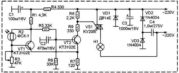
The scheme is designed to automatic switching of street lighting after dark and automatically turn off at dawn.
Schematic diagram shown in the figure. The level sensor light - photoresistor R2 type FSK-1. It is included between base and collector of transistor VT1, so in the afternoon, when the resistance R2 low this transistor opens as the voltage at its base increases. In the result, the voltage at its collector drops and the transistor VT2 is closed. The voltage on the collector increases, respectively decreases and the voltage between the control electrode of the triac VS1 and plus power, so it closes and the voltage on the lamp H1 lamp not arrives.

With decreasing light level, the resistance of the photoresistor increases, and nightfall at some point, the transistor VT1 is closed so that the voltage on the collector becomes sufficient to open transistor VT2. Voltage at the collector of VT2 decreases, what causes the increase in the voltage between the control electrode of the triac and the positive power supply to such a level that the triac is opened and turn on the lamp of H1.
Unlike many other simple circuits photoelectric, in that you can use photoresistor nominal resistance within a rather broad range almost from tens to hundreds of ohms. The voltage on the base transistor VT1 is determined by a divider of R3 and R2. When this resistance R3 AC, and it can be used scheme to adjust not only to work with photoresistor almost any nominal resistance, but almost any threshold natural illumination.
Additionally to to eliminate the flashing of the lamp with the rapid changes in illumination, as well as to not to prevent the unstable state of the circuit in the switching threshold, in the scheme of vedène delay and hysteresis. The hysteresis depends on the resistance R7, by him to the minus of the power supply connected to the emitters of both transistors, when they open VT2, the voltage at R7 increases and shifts transistor VT1 even more towards a closed state. Thus, this transistor trigger Schmitt. Circuit R5-C2 delays, in time, the switching of the Schmitt trigger excluding the photoelectric reaction on rapid changes of illumination.
The power supply is transformerless, with parametric the stabilizer Zener diode VD1 and reactance of capacitor C4. Rectifier diode VD2 and VD3.
Fixed resistors MLT-0,125 or similar import. Variable resistor R3 type str, but any how variable and trimmer, indicated on the diagram resistance.
The Zener diode is any to a voltage of about 15 V. the Diodes VD2 and VD3 - any reverse voltage of not lower than 400 V.
Electrolytic type capacitors Jamicon, but you can use K50-35 or any other counterparts. Capacitor C4 is imported film designed for AC voltage 275 V (AC275V), please consider this attention, as domestic capacitors of the same type, for example, K73 marked at the maximum continuous voltage, so if the capacitor domestic, then it needs to be a voltage lower than 400 V.
Transistors - any KT315 or KT3102.
During installation you need try to direct light from the lamp falling on the photoresistor, otherwise the scheme will not work correctly.
Author: Say V.


