


")

When a cold is usually doctors recommend to warm up the area of the nose and the nose with the help of a bag of hot sand or medical reflector. But here's the problem: bag all the time to hold hands and to periodically change cooled the sand and the heat from the reflector heats not only the nose but the whole face, Yes, the lamp light is blinding. Heating pads are too uncomfortable - too big. But perhaps the most significant drawback of all mentioned devices - the lack of ability to smoothly adjust the temperature warming up.
Electronicsarena with a thermostat, the description of which we offer readers, specifically designed for the heating of the area of the nose and the bridge of the nose. Powered device via a step-down transformer from AC a voltage of 220 V. the Maximum power consumption is less than 30W.
The heating temperature can be easily controlled and does not exceed 60°. Heating elements are metal film resistors. The thermostat is a thyristor device with pulse-phase control (Fig 1). Changing the time unlocking regulating thyristor V5 relative to the voltage transition on its the anode through 0, we thus changing the conductivity of V5 during the period voltage, rectified by the diodes V1-V4. This changes the energy input to the heater, assembled on the resistors R1-R7, and hence the temperature heating.
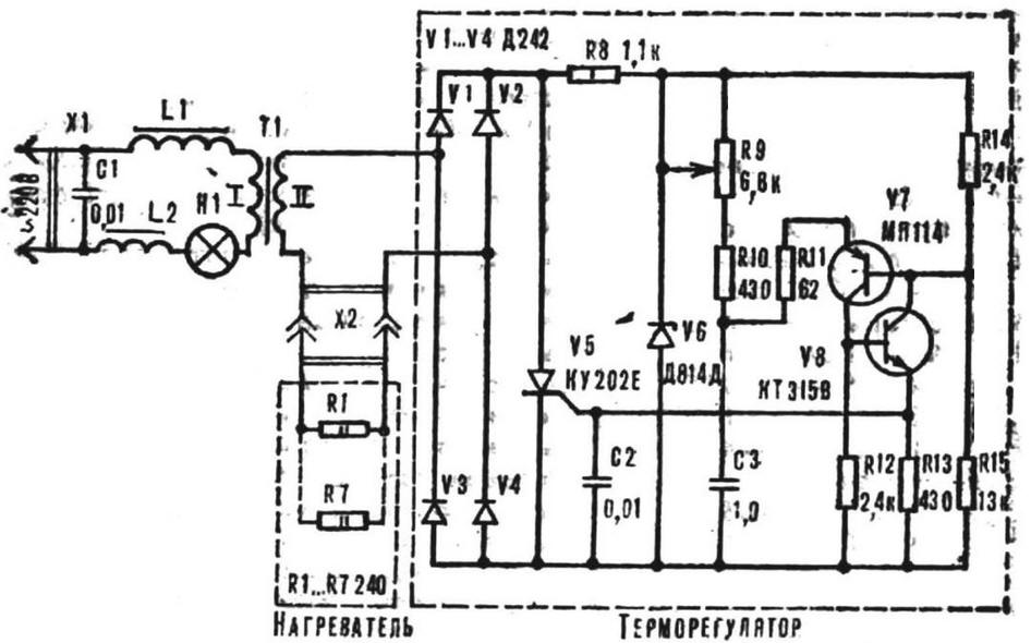
Fig. 1. Scheme of electronography with thermostat
Driver control pulses for the thyristor is made on the basis of analogue unijunction transistor on a semiconductor triode V7, V8. From the beginning period until the capacitor C3 has charged to the threshold voltage, almost equal to the voltage drop across the resistor R15, the transistor V7, V8 are closed, closed and the thyristor V5.
After charging C3 to the threshold voltage V7, V8 are opened, and managing the transition V5 receives the control pulse, the Thyristor is unlocked and remains open up to the moment of transition of the voltage at its anode through 0.
The charging time of the capacitor C3 and, therefore, the closed state thyristor V5 depends on the value of the variable resistor R9. Therefore, by rotating the handle R9, it is possible to vary the charging time of the capacitor C3 to the threshold voltage. And this leads to a change in conduction time of the thyristor V5 and therefore the power input and heater.
Because when the pulse controller having interference, the device there is a filter C1, L1, L2, preventing the penetration of noise into the network.
The design used the following details: R9 - variable resistor SPO-0,5, R8 - permanent MLT-1, others - VS-0.125 or MLT-0,25. Capacitors: C1 - MBM at 750, C2 - BM-2 for 200, C3 - MBM 160, N1 - incandescent MN 6.3 x 0,22.
Inductors L1 and L2 have gorshkoobrazny cores B ferrite brand and MNM contain 110 turns of wire sew-2 0,31. They can be replaced with round ferrite rods MN Ø 8 mm, length 25 mm. Transformer T1 is made on the yoke SH. The winding of I contains 2500 turns of wire sew-2 0,23, winding II has 295 turns of PEV-2 0,67.
Diodes D can be replaced by CDA, KDV, KDD, CDG, KDM, or CDR DB. Instead KUE possible to use thyristors CUI, COOL or CON. Transistor MP valid substitute for CHM 115, CTA or CTB and KTV - on CTA, CTG, CTG.
Heater cut out of sheet copper thickness 0.4-0.8 mm two figures drawing 2 and solder resistors between them OMLT-2. Then both conductive plates connect the two wires mgshv 0,75 length of 1.5-2 m for connecting heater to the thermostat.
Fig. 2. Heater
Next curly copper strips with resistors curve the shape of the nose, wrap three layers of fiberglass cloth and panel. To the corners of the heater attach ribbon or a rubber band, a width of 10-30 mm for fixation of the heater on face.
On the front panel of temperature controller, made of transparent Plexiglas installed sockets for the connection of the heater, removed the knob temperature (R9) and drilled the window under the lamp of H1. Inscriptions in ink on the sheet of paper which is mounted on the reverse side of the front panel.
Installation of the electronic unit is on the circuit Board, made of fiberglass thickness of 1.5 mm (Fig. 3).
Fig. 3. Circuit Board of the thermostat arrangement of parts
The thermostat is assembled in a plastic housing with internal dimensions HH mm (Fig. 4).
Fig. 4. The design of the thermostat: 1 - top stand, 2 - screw MH, 3 - lamp, 4 - housing, 5 - mounting plate, 6 - nut M5, 7 - nut M6, 8 - hour bottom, 9 - M3 screw.
The printed circuit Board is attached with studs M3 and struts (Fig. 5).
Fig. 5. Strut: a - upper, b - lower
To use electronography very simple. The thermostat include network, connect heater to it and fix it in the nose area. Rotating the handle 'Temperature', select the desired heat level.
Attention! Before you start to use made by electronography, always consult doctor.
Author: A. Rubanov