The device, which will be discussed, will help a person with impaired vision is not only time to detect the obstacle and evaluate "NAA hearing distance, but and determine the light level where it is located.
Among the devices that facilitate the orientation of the blind, give the best results portable active locators obstacles. They radiate in the direction of the possible obstacles probe ultrasonic or electromagnetic signals. Taken reflected from obstacles locator signals converts into a form available for perception to the blind, sound or vibration.
Devices, using as the probe radiation from the IR range waves, proposed quite a long time [1]. About one of variants of such a device, suitable for self-production, was presented in [2]. To the disadvantages of this design include a small range (only 1.5 m) and poor immunity. Just as an obstacle, the device reacts to being far beyond the customary lighting of the lamp filament. In the following proposed design, these drawbacks are eliminated due to the use in the receiving part of the selective amplifier. The added node that evaluates overall lighting and audible signals, indicating the presence obstacles and characterizing illuminance, easily distinguishable by ear.
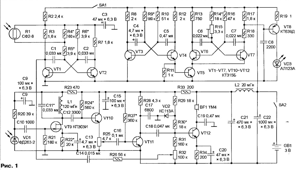
Diagram of the device shown in Fig. 1. The choice of element base of transistors due to the small range circuits operating at supply voltage 2...3 V. in addition, in the design of discrete elements is easier to achieve minimum current consumption. In this case it does not exceed 5 mA.

(click to enlarge)
Every 0.5 sec emitting diode VD3 sends a pack of pulses of IR radiation duration of 20 MS. The continuous refusal of the radiated signal is still one measure is the reduction in average current consumption. Generator sets the duration of the packets and pauses between them, assembled on transistors VT3 and VT4. Pulses with its release coming to the base of transistor VT5, including on and off the multivibrator transistors VT6 and VT7, and it generates pulses with a duration 58 ISS. A trimming resistor R15 set the pulse repetition frequency equal to the centre frequency of the passband of the selective amplifier at reception part of the device (2800 Hz). To achieve the required frequency stability, capacitors C6 and C7 should be small TKE. Apply ceramic capacitors groups H30-N is not allowed here.
A pulse frequency of 2800 Hz fed to the power amplifier transistor VT8, the collector circuit of which includes emitting diode VD3. Diode current pulse up to 300 mA. To absorb the heat-emitting diode the necessary heat from a material with high thermal conductivity. In this case applied copper area of 3 cm2.
Reflected from an obstacle, the infrared pulses taken by the photodiode VD1 and reinforced selective amplifier transistors VT9-VT12, is heard in the earphone from BF1 a hearing aid. The volume signal is greater, the closer is reflective object. In the above the burst duration of human hearing subjectively perceives it painted in a tone, not just as unpleasant click.
The gain of the receiver 2300, bandwidth (at the 0.5 level) - 300 Hz. The greatest contribution to selectivity makes a resonant circuit with L1C11 the resonant frequency of 2800 Hz. In order not to degrade its quality factor, the transistor VT10 connected in the circuit with a common collector. The oscillating circuit is small q, tuned to the same frequency, form coil earphone and BF1 capacitor C19.
High input impedance low-noise field-effect transistor VT9 is the optimal load for the photodiode VD1. When the photodiode is dark, tension noise given to the input of the amplifier does not exceed 0.9 mV. Approximately so is the hearing threshold of the reflected signal.
Receiver sensitivity adjust variable resistor R25.
The multivibrator transistors VT1 and VT2 generates pulses, the frequency of which the higher, the more light is included in the base circuit of the transistor VT2 photo resistor R1, sensitive to visible light. The pulses arrive at the base transistor VT12 . The result is reflected from obstacles, the signals are heard in the background low frequency sound from 100 Hz at an illumination of 1 l to (almost complete darkness) to 1000 Hz at an illumination of 1000 Lux (incandescent lamp power 75 W for a distance of several tens of centimeters). The volume of the background adjust variable resistor R32. If necessary, the node estimates the illumination can be disconnected the switch SA1.
The device is assembled in body size 120x90x30 mm. Its weight along with the source power - two batteries of size AA - Emitting 250 g the VD3 diode, photodiode VD1 and photoresistor R1 is equipped with lenses of organic glass. The width of the zone in which it's possible to detect obstacles, approximately 20°. The parts marked in Fig. 1 star pick up if desired the time adjustment device.
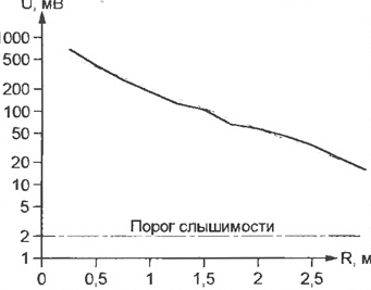
The solid line in figure 2 shows experimentally filmed dependence voltage signal U on the findings earphone BF1 and distance R from the reflecting IR the emission rights at the maximum sensitivity of the receiver and the nominal power supply voltage (3 V).

Subjectively, at the average rating of a few people with normal hearing, sound level shown in Fig. 2 interval the range varied from very loud (close to the pain threshold) to the Pacific. Dashed line is the result of averaging the experimental data. When discharged to 2.2 In the battery GB1 signal voltage has decreased by no more than two times.
Literature
Authors: A. Gavrilov, A. Teres, Tallinn, Estonia


