The simplest ozonizer consists of two dielectric conductor, separated by an air gap, which when applied to the conductors AC the voltage and the formation of ozone in the process of "quiet" discharge. Designs of ozone generators there are many - depending on the area use and objectives. Ozonators disinfected water in the city the water supply system, provide ozone chemical reactions and so on. Including sterilize the air of residential and industrial premises.
Here is one of such designs, created by a team of production technical Association "Avtotransservice" and more than a dozen years ago protected inventor's certificates and foreign patents.
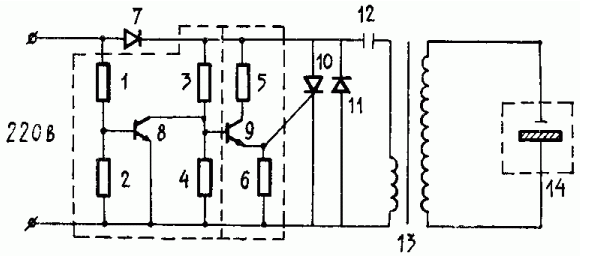
Schematic diagram of the control device represented in figure 1 (and.with. 637031).

Fig. 1. The device is running the generator ozonator: 1..6 - resistors; 7,11 - diodes; 8,9 - transistors; 10 - thyristor; 12 - condenser; 13 - increase transformer; 14 - ozone generator
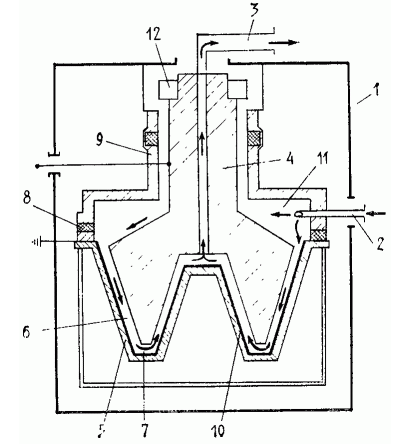
The ozonator (and.with. 768751) is very compact, which is achieved by the use of plate electrodes forms. Add - and high-tech. The manufacture of such electrodes with the modern development of cold forging special is not working. Characteristically, the performance of the device is not regulated in the voltage, and the magnitude of the air gap. Ozonator allows get up to 4 grams of ozone per hour, which is sufficient for the ozonation of the room a volume of 40 thousand cubic meters.

Fig. 2. Ozone generator: 1 - casing; 2 - air supply pipe; 3 nozzle exit ozone; 4,5 - electrodes; 6,7 - gap; 8 - insulation ring; 9 - flange; 10 is a dielectric layer; 11 - the settling chamber; 12 - the device changes the electric field due to the vibration.
As a principal diagram of an ozonator, you can use the scheme from ionizer ion-1.
Author: B. Rudenko


