


")

This device will useful for cleaning the air or kill bacteria in infectious diseases. A small concentration of ozone allows also to improve long the storage of products, for example in the basement.
In the basis of the instrument uses a property of air at the passing of an electric spark to form a new substance is ozone. When normal conditions is a gas having characteristic smell (ozone molecule consists of three atoms of oxygen and natural conditions in the upper layers the atmosphere and formed by atmospheric discharges).
As strong oxidizer, ozone kills bacteria and therefore can be used, e.g., for disinfection water and disinfect the air. But should know that ozone is poisonous and extremely valid is the content within the air 0,00001%. At this concentration is well felt his scent.
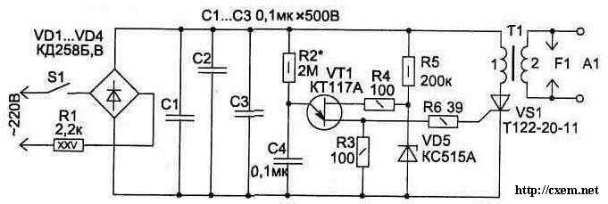
The circuit device (Fig. 6.21) on the emitter A1 is formed an electric the arc, through which passes the air stream. For the formation of uniformly distributed the arc on the radiator should get high voltage (15…80 kV) sufficient power. This is done by using the Converter circuit and the transformer T1. In the primary winding T1 the thyristor VS1 generates pulses at the expense of discharging capacitors C1…NW through the winding. Controls the operation of the thyristor oscillator transistor VT1. Resistor R2 is chosen so as that is, when the voltage on the capacitors C1 NW… reach 300 In (due to the charge from the network), opens the thyristor VS1.
The device is not critical to details, and the resistors may have values of, similar to those presented in the diagram. Capacitors C1…NW type MBM, CU-2, working voltage not less than 500 V, C4 - K73-9 at 100 V. the Diodes VD1 VD4… you can replace the Assembly CCJ, V.
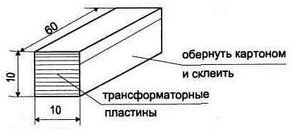
High voltage transformer T1 is made on the plates of transformer iron, dialed in the package (Fig. 6.22). This design allows to exclude the magnetization of the core. Winding is round: first the secondary winding - 2 - 2000 turns of wire PEL diameter of 0.08…0.12 mm (in four layers), then primary - 1 - 20 turns. Interlayer insulation is best done from several layers of thin (0.1 mm) PTFE tape, but the suit also capacitor paper (it can get out high non-polar capacitors).
After winding the windings the transformer should be filled epoxy glue. In the adhesive before pouring it is desirable to add a few drops condenser oil and mix well.
For ease of fill, you to make a cardboard frame dimensions transformatora, where you sealed.
Made this the transformer provides in the secondary winding voltage amplitude over 90000 In, but to include it without protective the spark gap F1 is not recommended, as when this possible breakdown within the coil. Protective gap is made of two bare wires located on a distance of 20…24 mm (for air breakdown the voltage is about 3 kV per 1 mm of the gap).
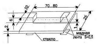
The design of the emitter A1 shown in Fig. 6.23. Design elements are mounted on the side plates of Plexiglas thickness of 5…10 mm (Fig. not shown). In the gap between the conductive plates and glass (1 mm) is formed uniformly distributed arc. It can be clearly seen when the darkening blue stripe and characteristic smell.
For greater efficiency operation of the device, you can use any the fan, for example of the type VN-2 - it will accelerate air circulation in the working area emitter.
The described apparatus creates a low concentration of ozone, and for freshen the air in a residential area it should work for 10…20 minutes.
Publication: www.cxem.net