


")

The healing properties of the air of forests, mountains, Alpine meadows, sea of humanity known for a long time. Even the ancient Greek physician Hippocrates noticed that mountain and sea air a beneficial effect on people, healing from many illnesses. The nature of the beneficial effects of such air scientists discovered Elster and I. G. Heitel. They found that the healing properties of ions in gases air air ions, as they later called A. Chizhevsky. Air ionization occurs under the influence of radiation of soil and water, ultraviolet radiation from the Sun, cosmic rays, electrical discharges in the atmosphere (lightning discharges on the mountain tops, the needles of coniferous trees, etc.), as well as the crushing action of water and its spray in a storm, rain, waterfalls. Air ions have a negative or positive charge.
Negative air ions are represented by oxygen, which easily captures free electrons from the outside. Positive air - carbon dioxide and nitrogen, if they are deprived of one of the electrons. Negative and positive air ions affect the body in man and animals varies. Chizhevsky in his experiments, found that negative air ions prolong life, and positive, on the contrary, shorten life. But more pernicious as affected animals, the air, devoid of all ions.
The air with an excess of ions of oxygen stabilizes blood pressure, makes breathing deeper, increases appetite and improves digestion. Air ions affect the physico-chemical properties of blood: erythrocyte sedimentation rate, concentration of sugar and cholesterol.
In the coniferous forest on a Sunny day, the number of ions reaches 10 thousand in 1 cm3 of air in to 20 thousand mountains, waterfalls up to 100 thousand Built houses, a man almost impossible to breathe ionized air. In a residential area the number of negative ions does not exceed 100…200 cm3. In the premises at the end of the day the number of negative ions decreases to 25…50 cm3. Negative air ions are practically absent near televisions, monitors, office equipment, in rooms with air conditioning and ventilation. In such areas at present mostly positive air ions for accommodation of a negative impact.
Almost all types of ionizers used fluvially method of air ionization. It is as follows. If the needle tip to apply a high voltage (minus the needle, and plus - on the ground), then the edge will "drain" the electrons ("effluvia" in Greek "expiration"). Moving electrons in its path "stick" to the oxygen molecules, forming negative air ions. A. Chizhevsky has developed a number of requirements to the ionizers, it is crucial that the ionizer is not produced ozone and nitrogen compounds. As ozone and nitrogen dioxides are strong oxidizing agents.
Amateurs design "Chizhevsky, which is used fluvially method of ionization. But as Amateur structures are very different from the one design, which was proposed by Chizhevsky, or low efficiency of aeroionizatora, or they produce ozone and oxides of nitrogen. So, the majority of designs, is a high-voltage unit based on the modified output flyback transformer of a television receiver by multiplying the voltage.
The design of the electron emitter has not received adequate attention. Devices for measuring the amount of ions in 1 cm3 of air yet. Such designs are well perform the function of air purification, but as aeroionotherapy - ineffective, as necessary for humans, the concentration of ions is created in them at close range-in the area of ozone formation. But there are structures capable of generating negative air ions without high voltage, due to balloffet (spraying water). This so-called hydromonitor. There are mechanical and electronic hydromonitor. The water spray is produced using ultrasonic vibrations of the piezoelectric concave plate placed on the bottom of the tank. Electric diagram of the generator of ultrasonic vibrations is shown in Fig.1.
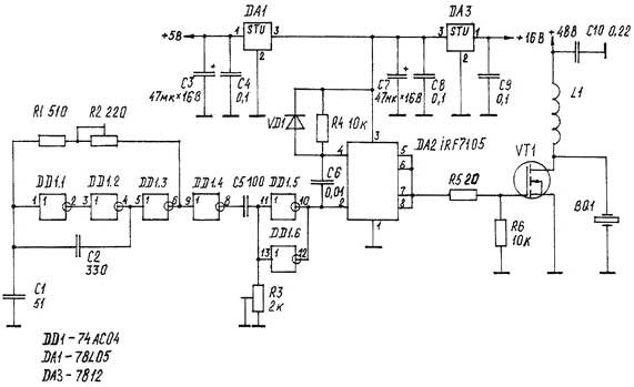
Fig. 1
On the elements DD1.1-DD1.3 is assembled, the generator of rectangular pulses at a frequency of 1.8 to 2.0 MHz. DD1 chip type AS on complementary field-effect transistors with the structure of metal-oxide-semiconductor, which is a version of a widespread series of transistor-transistor logic SN74, allowed to obtain a steep wavefronts, low current consumption, small values of the frequency-setting elements in comparison with the generator on the chip SN7404 (CLN). The element DD1.4 - buffer. Output DD1.4 pulses go to the differentiating circuit C5R3. Changing the time constant of an RC circuit with a trimming resistor R3, it is possible to change the pulse duration at the exit of the element DD1.5, DD1.6, therefore, will vary the duty cycle from 0 to 2.
Thus, the regulated power supplied to the piezo oscillator BQ 1, and the number of generated negative ions. Since the threshold of opening a powerful MOSFET-transistor VT1 about 5 In, and for quick opening and closing of the transistor need large currents, it is necessary to use the amplifier. As he applied the chip DA2 IRF7105 consisting of two field-effect transistors: n-channel and p-channel. Characteristics of n-channel transistor: drain current 3.5 A power dissipation of 2.0 watts. Characteristics of the p-channel transistor: drain current 2.5 A, power dissipation of 2.0 watts. This amount of current at a voltage of 12 In DA2, just enough to quickly recharge the input capacitance of the MOSFET transistor. When a low logic level at the output DD1.5, DD1.6 open the p-channel transistor in DA2. In this case, the gate of the transistor VT1 through the resistor R5 is supplied +12V, and the VT1 transistor opens.
When a high logical level at the output DD1.5, DD1.6 open n-ka-tional transistor in DA2. In this case, the gate of the transistor VT1 through a resistor R5 is connected to the common terminal of the power source, and the transistor VT1 is closed. Gated MOSFET-transistor static charge capacitance of the piezoelectric element BQ 1 through the inductor L1. When you open the transistor VT1 static capacitance of the piezoelectric element BQ 1 discharged. Wherein the piezoelectric element is deformed. The oscillations of the piezoelectric element at an ultrasonic frequency to create in the fluid a longitudinal elastic wave.
When the location of the piezoelectric element on the bottom of the tank and filling it with water to a level equal to the focal size of the piezoelectric element, with the surface of the water will rise a small fountain, accompanied by a mist of fine drops of water. These drops of water are carriers of negative ions. In design (Fig.2) used emitter concave shape with a diameter of 30 mm and a focal distance of 70 mm from the PZT piezoceramics at the frequency of 1.8 to 2.0 MHz. In brass body 1 is glued using a conductive adhesive, the piezoelectric element 2. It further below pressed nylon ring 5. The housing is mounted on the bottom of the tank 4 with brass ring 10 and the sealing rubber ring 3. From the bottom to the ring 5 is pressed against the nylon bushing 11 massive brass washer 6, which functions as a heatsink for the transistor 7. The washer has a hole for conductor connecting the piezoelectric element with the drain of the transistor. MOSFET transistor mounted on the heat sink via an insulating gasket. Board with radio elements 8 are pressed nylon bottom ring 13. In the lower part of the housing 1, on its outer side, is located the inductor 1 2 (L1-scheme), wound on a frame made of dielectric. The power from the rectifier is supplied by a two-wire shielded cable 14 through the Central opening in the cover 15 of the housing 1.
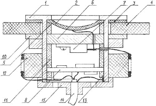
Fig. 2
Setting of the electronic circuit is as follows. In the first place, separately from the power transistor to adjust the generator frequency of the parallel resonance of the piezoelectric element BQ 1 via the resistor R2. Resistor R3 sets the output DA2 minimum pulse duration. Then install the Board into the case and make all connections.
The installed capacity of the corps to defend the water is poured. The filling level of the tank is not higher than the focal length of the piezoelectric element. Apply mains voltage to the circuit from the source with a current limit. Controlling the voltage of the oscilloscope to the junction point L1, the drain of the transistor VT1 and the piezoelectric element BQ 1, by increasing the power the resistor R3 to achieve amplitude signal 120 V peak to peak. Frequency control resistor R2 to achieve minimum consumption of current from source +48 V. As a rule, there is the education of the greatest number of negative ions. The design of the PCB.
The radio components are installed on a round PCB from bilateral foil fiberglass. Installation is made on both sides of the Board. Chip DD1 and DA2 in the SMD version. Fixed resistors sizes 1206, can be mounted vertically resistors C2-23 power 0,062 W. Trimmer resistors R2, R3 type SDR-19a. Constant capacitors ceramic size 1206. Electrolytic capacitors firm HITANO series ESA. Diode VD1 any pulse type KD522. MOSFET-type transistor VT1 IRF630S, IRF730S in the case D2-PACK or similar, the n-channel. Coil L1 consists of 15 turns of wire sew-2 with a diameter of 0.8 mm.
According to the magazine, glad I oamator
Publication: www.cxem.net