


")

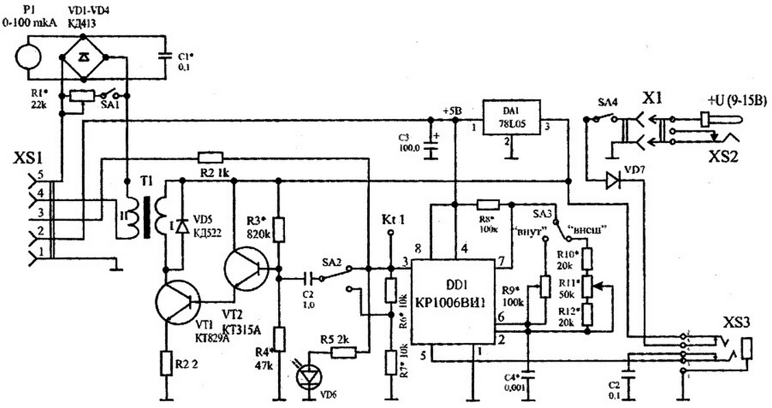
Block of reflexology acts as a generator reflexionando. Consists of of rectangular impulses generator and power amplifier.
The generator of rectangular pulses DD1 is implemented on the IC timer CREW, included in the model scheme. When the "inside" of the switch SA3 frequency generation is determined by a multi-turn trimpot resistor R9 and capacitor C4 and ranges from 10 to 20 kHz. When set to "EXT." switch SA3 frequency of oscillation is determined by the size of slide variable resistor R11 and capacitor C4.
The voltage output from the generator (vyv. 3 DD1) is input to the power amplifier, implemented on transistors VT1 (CTA) and VT2 (CTA). In the collector circuit transistor VT1 is connected to the transformer T1, which are used core Sh,5 mm. Primary (I) the coil has 500 turns of wire sew-1, diameter of 0.23 mm, and secondary (II) - 3000 turns of wire sew-1, with a diameter of 0.1 mm. the output Voltage of the transformer T1 at a load of 1 Mω is not less than 50 In (EF.) at a frequency of 10-20 kHz. Switch SA2 is used to switching of the output level. The parameters of the voltage divider R6-R7 are selected based on the minimum voltage at the output of the unit (optional by).
When possible repetition of the device design is desirable the possibility of modulating the voltage at the output of the block.
Non-standard 5-pin connector XS1 connect an external remote devices.
A circuit diagram of a block of reflexology is shown in the figure.
(click to enlarge)
Indicator P1, together with the bridge VD4 VD1…is used to estimate the magnitude of the output current. The circuit uses a dial type indicator sensitivity M 0-100 μa, the resistance of the frame 2750 Ohms. The switch SA1 is used to change the limits of measurement P1 to 5 (or 10 mA). The multi-turn resistor R1 type SP5-3. Led VD6 is to display the voltage at the input of the amplifier power. DA1 chip (type 78L05) is a voltage stabilizer power +5 V. Socket XS2 (type DJK-07) connect an external source power. Schottky diode VD7 (type 1N5717) serves to protect the circuit from wrong connect to a power source of a different polarity. Switches SA1…SA4 -slide type PD-9.1. The majority of fixed resistors and capacitors - chip, size 1206. All elements are placed on two PCBs with size 46x94x1,5 mm (bearing) and 46x50x1,5 mm.
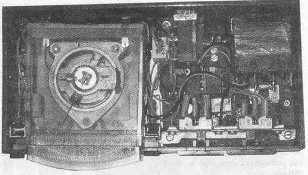
The appearance of the block of reflexology from the installation is shown in the figure.
Block of reflexology may operate in a standalone mode, and when the management from the main unit. In this case, the block of reflexology connects 3-wire cable through XS3 connector (type agricultural cooperative-3.5-30) to the connector XS2 main block. The control is provided by the pin. 5 DD1 chip.
The block diagram of reflexology does not require any special setup. Correctly assembled unit works immediately. The process of adjustment of the device is reduced to selection of capacitor C4 and resistor R9 for the purpose of receiving frequency 10-20 kHz generator and choosing the value of resistor R3 with the aim of obtaining the maximum output voltage of the device. The inspection is carried out by using standard measuring instruments such as oscilloscope and the frequency counter.
When configuring the unit sometimes requires the selection of component values, marked on the circuit diagram of an asterisk (*).
The current consumption of acupuncture depends on the output load. When the supply voltage is 9 V when using the "regular" remote devices is not more than 150 mA.
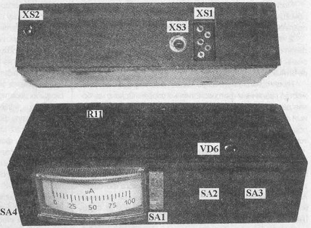
The appearance of the block of reflexology is shown in the figure.
The device is housed in a plastic housing. Dimensions: 48x97x24 mm Weight, not more than 130 g
Literature