In January and February issues of the journal "Radio" the current year was told about the unique invention of our compatriot A. L. Chizhevsky - aeroionizatore, later called "Chizhevsky Chandelier". To the editor calling and writing hundreds of readers interested in this setup, and is able to create a sitting area with mountain air. Today's story is dedicated to two embodiments of the high voltage needed to power elektroefflyuvialnaya chandeliers-generator of negative ions.
As already reported in [1] applied to electroepilation chandelier DC voltage of negative polarity should not be below 25 000 In, otherwise the desired effect of aeroionizatora will not. Therefore, any power supply, assembled as published in [1, 2] schemes or independently designed, should meet this essential requirement.

Fig.1
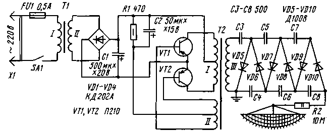
Diagram of one embodiment of such unit is shown in Fig. 1. This voltage Converter is made of two powerful transistors VT1, VT2. They work in the generator, assembled push-pull circuit. The collector terminals of transistors is connected to the winding I of the transformer, and the conclusions of the base - winding II. Self-excitation of a generator arises from a positive feedback between the collector and base circuits of the transistors. This process also contributes to the chain R1C2 that determines the mode of operation of the transistors.
As a result, the excitation of the generator at the terminals of the winding of the I variable appears (or rather pulse) voltage frequency 3000...4000 Hz. It increases hundreds of times the output winding III and is fed to a rectifier of the circuit multiplication of voltage on high-voltage diodes VD5-VD10 and capacitors NW-C8. Rectified voltage of negative polarity is supplied to the chandelier through a current limiting resistor R2.
To power the generator used a rectifier on a powerful diodes VD1-VD4 bridged. Rectified voltage is filtered by capacitor C1. AC voltage at the rectifier is removed from the secondary winding of the step-down transformer T1.
The primary winding of the transformer is connected to power supply through the fuse FU1, the switch SA1 and plug X1.
The transformer T1 can be made independently on the magnetic core of the transformer iron s with the thickness set to 30 mm. Winding I must contain 2200 turns of PEV-1 to 0.25, winding II -120 turns of PEV-1 to 1.2. For a more accurate selection of the rectified voltage, it is desirable to make bends of 90, 100, 110 turns. Fit and ready transformer with a voltage in the secondary winding 10...12 V at load current up to 2 A.
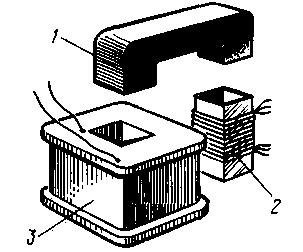
Transformer T2 is made on a ferrite magnetic core from a TV flyback transformer FA series, consisting of two halves (1) - Fig. 2.

Fig.2
High-voltage winding (3) wound on the frame, glued the PCB, fiberglass or organic glass with a thickness of 1 mm. the Width of the frame - not less than 30 mm. Winding must contain 8000 turns of wire PELSHO 0,08-0,1. In the extreme case will fit the wire sew or PEL. Every 800 turns it is necessary to lay a thin layer of PTFE tape or cover the coil melted paraffin. You should strictly ensure that the turns of the upper layers weren't on the bottom.
For primary winding (2) will need a sleeve, which can be glued together out of cardboard. Winding I must contain 14 turns of PEV-1 to 0.8 with a branch of the middle and winding II - 6 turns of the same wire with a branch from the middle. The winding is preferably covered with paraffin and wrap with tape.
In the frame and the bushing insert halves of the magnetic core and pull them together (this is where the old mount flyback transformer).
The generator transformer is allowed to be wound on the magnetic core of transformer iron s, the thickness of the dial 30 mm. In this embodiment, making the frame out of cardboard, Micarta or fiberglass. First wound windings I and II (respectively 20 turns of PEV-1 to 1.2 and 16 turns of PEV-1 0,5 - both with a branch of the middle) and cover them with paraffin. In addition, they reel up a good layer of insulating material, such as PTFE tape with a thickness of 1 mm. Then the winding is wound III - 7000...8000 turns of wire PELSHO of 0.1. Here, too, after every 800 turns coat the coil with paraffin.
Oxide capacitors - any series, resistors - MLT. Options high voltage capacitors and diodes can be found in [1,2]. Diodes bridge rectifier can be replaced with a current capacity not less than 2 And, for example, KD202. CD. CD, CD, D-D with any alphabetic indices. Also indicated in the diagram, suitable transistors CT with any alphabetic indices, CTA-CTV and even any P (except PG). For transistors must be fabricated from sheet aluminum or duralumin thickness 2-2,5 mm radiators with an area of 60...100 cm2.

Fig.3
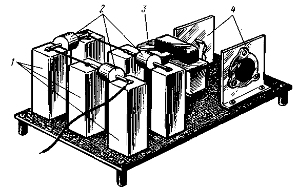
Possible variant of the mounting device shown in Fig. 3. High voltage diodes D (1), capacitors COBB (2), self-made transformer (3) generator and specified in the diagram, the transistors with the heat sinks (4) are mounted on an insulating Board (but not from organic glass!) 2.5 mm thick, which is then placed in the housing of insulating material (organic glass, epoxy, plastic).
Special attention should be paid to the installation of diodes and capacitors. The conductors connecting between them should be short and brazing - flat and smooth. Sharp edges and protruding ends soldering wires carefully smooth out a needle file to prevent the possibility of corona and the smell of ozone.
Rectifier with step-down transformer is collected in a separate structure, but it is possible the placement of its parts in common with the generator Board. In this embodiment, the switch SA1 is advisable to mount near the power outlet.
Verify the operation of aeroionizatora start with the rectifier. Instead of the generator output (in parallel with the capacitor C1) is connected as a load resistor of 8...10 Ohm 25 W (resistor sew or self-made from thick wires with high resistivity). Include plug X1 into the network and serves the voltage through the switch SA1 of the transformer T1. Measure the DC voltage on the load resistor should be at least 10 V.
Further connected to the generator rectifier. If it is assembled correctly and the details are intact, you will hear a subtle squeak of the high voltage transformer. Otherwise you need to reverse the extreme terminals of the winding I or II, and perhaps also pick up a resistor R1. When you see a sharp squeak or clicks breakdown should reduce the voltage of the generator is to solder the rectifier to one of the taps of the transformer with a lower voltage.
Convinced of the absence of corona, which include installation in the darkness, eyeing the high-voltage parts. If the findings of the details appear purple lights - a sign of corona. Soon will feel the smell of ozone. Setting off, inspect the rations, if necessary, smooth out the sharp edges and cover the corona conclusions of melted paraffin.
The final stage is the control of high voltage by the method described in [1].
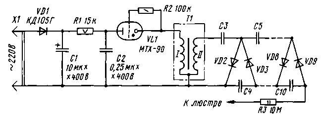
After that, the generator with multiplier set near chandelier and connect the output wire of the multiplier (left circuit output resistor R2) to the chandelier. The ground wire (from the bottom of the output winding III of the transformer T2) is connected to the water pipe or heating. If the rectifier transformer are mounted in a metal enclosure, it is also grounded. Diagram of another version of the PSU chandelier shown in Fig. 4. In principle it is not very different from those described in [1].

Fig.4
Mains voltage is rectified by the diode VD1. Rectified voltage is filtered by capacitor C1 and fed to the charging chain R1C2. As the voltage on the capacitor C2 reaches the ignition voltage of the thyratron VL1, he erupts. The capacitor discharges through the primary winding of the transformer T1, the thyratron is extinguished, the capacitor again begins to charge, etc.
Eye-catching, the secondary winding of the high voltage pulses arrive at the already known voltage multiplier (it consists in this embodiment of the eight cascades), and released on the chandelier.
Rectifier diode - favourite, designed for reverse voltage not less than 600 V and a current not less than 30 mA. Capacitor C1 - oxide, C2 - paper specified in the scheme nominal voltage. The resistor R1 is permissible to make three parallel connected resistance 47 kOhm. Transformer T1 is an automotive ignition coil. Instead of thyratron you can include one or more diacs series KN - picking up the total voltage of inclusion, it is easy to adjust the high voltage to the chandelier.
Literature
1. Ivanov B. "Chizhevsky Chandelier" with their hands. Radio, 1997, No. 1, pp. 36, 37.
2. Biryukov S. "Chizhevsky Chandelier" with their hands. Radio, 1997, No. 2, pp. 34, 35.
Author: Ivanov, Moscow; Publication: N. Bolshakov, rf.atnn.ru


