


")

Many stores are available in cushion-massagers in the chair. The principle is simple: in a cloak on a chair mounted 5-7 vibrator motor whose operation is controlled by the remote. The disadvantage of this system is that the work programme of the motors incorporated initially and does not depend on external factors.
Not whether to make the scheme, which will include a particular bustline depending on the appearance of a certain frequency from the speaker of the tape recorder or radio? In other words, the seat will vibrate to the beat of the music, thereby causing the feel the music back.
The idea I implemented a method to create two blocks: color box 3 channel amplifier for it. Scheme and recommendations for it below.
(click to enlarge)
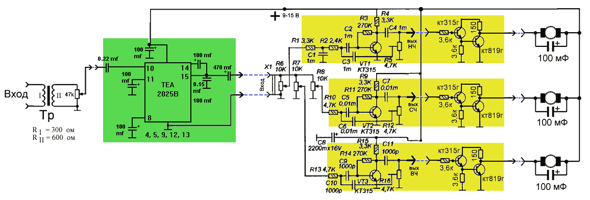
As can be seen, the scheme consists of two parts: the amplifier and the console, which in turn is divided into 3 filters low, medium and high frequencies.
In principle, you can do without the amplifier, but in this case with a weak signal sources (for example linear output), the system will not work.
The signal will take from the speaker of the tape recorder (car). To prevent distortion and overloads the signal from the speaker will be tied up through a transformer. In principle, any. I took matching transformer with the impedance of the primary winding 300 Ohms, secondary - 600 Ohms. Resistance of 300 Ohms will not affect the sound from this speaker.
Next, the signal goes to the amplifier assembled on a chip TEA2025B (analogues КА2206N, TA7769). The amplifier consumes from 3 to 14, giving a capacity of 2 watts. This is enough to work with colour and music consoles. From 12 to 14 In the chip heats, so you should make it a little cooler.
The next step is the creation of filters for color consoles. I took proven an elaborate scheme from the magazine "radio construction set" No. 7 in 2005, the Only thing added is a composite transistor (KT315 and CTG). The fact that the vibrator motor have quite a lot of power and, accordingly, they need a power transistor. Transistors CT G it is desirable to make on the wires, and placed on the radiators, but given the fact that the body of the transistor is it the Manifold, so contact transistor package is unacceptable.
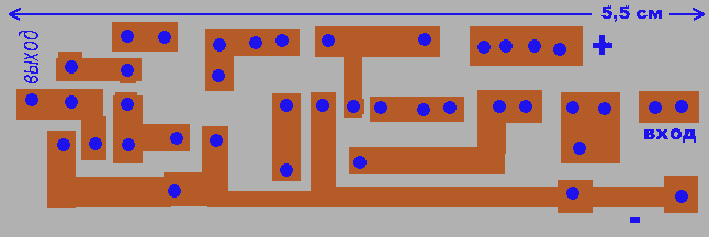
All 3 filters have almost identical layouts, so I drew cost (from the tracks), which is suitable for all 3 filters.
In this scheme, each filter has its own settings. The variable resistors R6, R7, R8 regulate the level of signal filters, and R5, R12, R16 - bandwidth. Such configurations are useful for the harmonization of this device with a specific receiver and preferences of the listener.
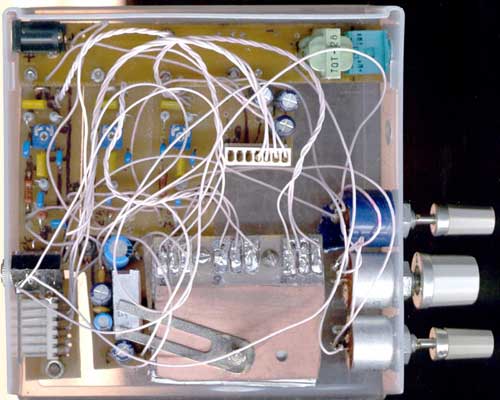
Next, you need to put on a small circuit Board connector for the seat-massager and capacitors. Various modifications of the chair-massager have different current consumption, so the capacitors in parallel with the motors chosen experimentally.
The last step is the connection of the chair. Parse the control panel from the seat-cushion and unsolder all wires running to the chair. Next you need to define a Common wire (+) from motors and the outputs from each of them. Typically, this common wire is thicker and has a black or yellow in color. Take the PSU and plus connected to this GND. And minus sequentially connected to each of the remaining wires. Thus, we will determine which of the motors acts on different points of the back.
Choose three motors in the chair-Cape, You the most preferred and plug wires from them respectively low, high and medium frequencies.
As you can see, in the chair involved only three of the vibrating motor, respectively low, middle and high frequencies.
If You think this is not enough, you can use the remaining vibrator motor from connecting in parallel. That is, each frequency will have 1-2 the vibration motor.
Author: Aleksey Gorelov, Bryansk; Publication: www.cxem.net