


")

Accept remote УSW FM radio stations can complicate or make impossible interference from local TV or УSW FM transmitter. Author of published articles decided the problem of the introduction of such interference at the input УSW FM Converter for notch filters.
The most simple passive single-link serial or parallel filters at 75 Ohms have a low q-factor I. therefore, too broad a strip of rejection. The best parameters are combined filters from series and parallel resonant circuits (Mishustin I. A. Improving the noise immunity of the radio reception. - M.: Energy, 1974). As shown practice, good quality has a notch filter L1C1C2 (Fig. 1,a). It Frequency response, taken by the device Kh1-7B shown in Fig. 1, b. The bandwidth of rejection by the level K = 0,707 is not more than 2 MHz at a depth of suppression of at least 25 dB.
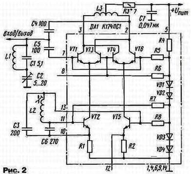
With all that said, it was designed УSW Converter stations in the range УSW-1 receiver with a range УSW-2 (Fig. 2). Input and output Converter combined, so that a separate antenna is required.
Technical features:
- The voltage, V......6 12…
- The frequency of the local oscillator, MHz......26
- The degree of suppression of an interfering signal, dB, not less......25
Heterodyne Converter transistors VT2, VT5 chips with DA1 minimum number castorocauda elements - L2, C3 and C6.
In this structure, the conclusions of the mixer 2 and 3 of the chip is loaded on a symmetric the coil L3. This provides a balance of pairs of transistors VT1, VT3 and VT4, VT6 differential cascade of direct and alternating currents and, as therefore, increase the sensitivity.
It is important to ensure and optimal value of the collector currents of transistors mixer affecting the noise level. Chip to CPS minimum level noise is achieved when the total current of the differential pairs of transistors is about 1 mA.
Input signal through the capacitor C5 is supplied to bases of transistors VT1, VT6. In differential stage it is mixed with the lo signal, is converted by frequency and is output through the capacitor C4. In the output spectrum has a summary component, which contains the signals of radio stations УSW-1, moved in the range of frequencies the range УSW-2.
In the Converter applied resistors MLT - 0,125, capacitors km or CT, C2 - trimmer type CT-21. For stability settings, it is desirable that capacitors C1 - C3 and C6 had the minimum value of TKE.
Coil oscillator coil L2 is wound to a coil on the frame 8 mm the podstroechnik armor from the magnetic core SB-1 and contains 5 turns of wire Sew or PEL with a diameter of 0.56 mm. the same wire turn to turn, but without the frame, mandrel with a diameter of 5 mm is wound катушкаL3 which contains 10 turns with a branch of the middle. Coil L1 is made by a wire with a diameter of 0.95 mm and contains 4 coil, wound on a mandrel with a diameter of 5 mm with a small step.
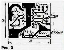
All items are placed on a single-sided PCB of foil fiberglass thickness 1…2 mm (Fig. 3). Elements of the local oscillator and input circuit separated by a printed conductor which acts as a "screen." In hole diameter 8 mm glued the coil L2. A hole diameter of 3 mm is intended for attaching the Converter to the chassis of the radio. The Converter is powered by radio stabilized voltage 6… 12 V and consumes current in 1.5…4 mA.
To configure the notch filter connected high frequency millivoltmeter to the exit path if of receiver. The AGC system (if any) should be disabled. Adjusting the radio interfering signal, the rotation of the rotor of the capacitor C2 achieve the minimum pocasie millivoltmeter. While fine-tuning filter the signal at the output tract of the if I should fall to 25…30 times. If such repression is not achieved, it should be closer to pick up the capacitance of the capacitor C1. When the absence of the instrument filter set "by ear" on the maximum suppression side channels of reception. Most of the side channels should disappear, and in their place to receive useful signals of radio stations УSW-1.
At the desired range are configured by the podstroechnik coil lo L2. focusing on frequencies known radio stations. Upon completion of this setting should pour all coils and podstroechnik coil L2 paraffin (or other moisture-resistant compound). Minimum noise level making the selection resistor R3. It is preferable to do it in the pause transmission when the noise is not masked speech or music signal. For precise adjustment of the resistor R3 can be composed of two, for example, parallel connected resistors resistance 10 and 15 Ohms.
Author: A. Pakhomov, Zernograd, Rostov region