Elimination of interferences in the range of SV - LW
The most simple filter that attenuates signals were approximately 3 to 10 dB more bass and less treble, depicted in Fig. 1.
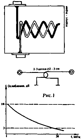
Fig.1
It is a two to three-loop connection, arranged one inside the other. With the help of this filter can be greatly diminished interference from powerful LW-SV stations. In severe cases you can try to use notch filters, i.e. filters that are configured on a particular interfering signal. The most simple filter looks like the one shown in Fig.2.
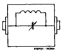
Fig.2
It is a circuit tuned to a frequency of interfering stations included in the antenna circuit. The best option - if the condenser air circuit. You can combine the methods shown in Fig.1 and 2. Band of rejection carefully executed loops can be 10 kHz, 1.6 MHz to 500 kgN, at 30 MHz. Filters are reversible, i.e. theoretically, there is no difference, where to connect the antenna and the receiver, but in practice it may be that the difference will still be although small.
Structurally, these filters are made in glass fibre laminate, carefully soldered boxes, after setting up the filter is useful to close the lid, and carefully solder. In some cases it may be necessary to use an attenuator with variable attenuation. It is convenient to use the device depicted in Fig.3.
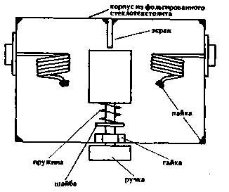
Fig.3
It consists of two identical coils with a diameter of 15 mm, with 5 to 10 turns and arranged parallel to each other, between which rotates the flap of foil fiberglass. When the perpendicular position of the flap relative to the turns of the coils attenuation is minimal, with a parallel arrangement-as much as possible. This attenuator provides initial attenuation of 3 dB and b end - to 20 - 40 dB, depending on the range it works "softer" than ordinary resistor attenuator. When a large number of interfering stations, the best solution would be the use of bandpass filters. The circuit used in the band filter should be as good. It should be noted that as in the notch and band filters is not recommended to use coils on ferrite cores. The use of coils without cores implies that they should to be made of thick wire, and that the capacitors used in these circuits should to be with an air dielectric. Me tested a simple version of a bandpass filter that uses only one variable capacitor, and this filter has a relatively narrow bandwidth (Fig.4).
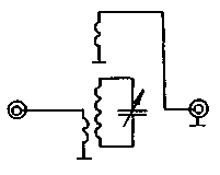
Fig.4
It is a customizable outline, placed in a glass fibre laminate box, with the two ends of the coil is a coil connection: single - antenna, the other with the receiver. The capacitor is preferably used with a maximum capacity of not more than 100 pF. In such a filter can also include a notch contours, as in Fig.2.
Elimination interference from УSW stations
Filters on lumped elements, it is difficult to achieve acceptable parameters when working on УSW. But УSW the need to rejective filters high. For example, in Belgorod local television station runs on 6 TV-channel, and the Kharkiv commercial television station - 7 TV-channel. Blocking local television station reception Kharkiv telecentre in areas near the TV tower is impossible. In such cases, it may be useful notch filter on long lines. It is a is in parallel with the input on the TV receiver open on the cut end of the coaxial cable length of a quarter wave interfering channel (Fig.5).
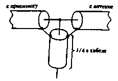
Fig.5
This section of the cable is almost a short circuit not only for its resonance frequency, but for all its odd harmonics. If one segment of the cable will not be enough for a satisfactory rejection of an interfering signal, you can include a quarter wave length of another segment, and so on (Fig. 6).
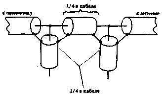
Fig.6
The calculation should take into account the velocity factor of the wave in the coaxial cable. For normal cable with polyethylene insulation, this coefficient is 0,66. To adjust the filter shortening of the cable, it is desirable to use a piece of cable with an initial length slightly greater than estimated. Departmental УSW stations operate in the range of from about 130 to 170 MHz. If it is not possible to know exactly the frequency of this transmitter, you can use a custom filter (Fig.7).
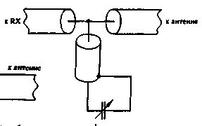
Fig.7
He represents a length of the cable is about 1.5-2 times less than a quarter of the intended wavelength for this filter. For example, in order to carry out rejectio in the range 130-mg, the cut length of the cable should bpy within 15cm. The condenser needs to be sure air with capacity of about 2...20 pF. Notch filters made of cable, if sufficient quantities can be used to NE-SW range with very good effect. In this case, it is desirable to perform adaptive jitter, as in Fig.7.
Filters with coaxial Rejectors can be turned on and the output of the transceiver by configuring part of rejection to hinder the reception signal and the part of rejection on the frequency at which the transceiver creates a hindrance. In this case, when receiving get rid of the interfering station, and when the transfer is interference from neighboring receivers.
Author: I. Grigorov (UZ3ZK), Belgorod; Publication: N. Bolshakov, rf.atnn.ru


