


")

It is known that multi-band amplifiers will significantly improve the sound quality sound-reproducing equipment. The separation of the frequencies in the AF amplifiers often just use RC-filters or complex active filters. According to the author, in circuit relation, especially in the formation of several frequency strips, much easier to use a LC filter. Variant of the AF amplifier in which apply the filter described in the article published below.
Circuit of the LC filter in the amplifying path shown in Fig. 1. The composition the filter includes an inductance coil Lф, the capacitance of the capacitor SF, the output the resistance of the cascade transistor VT1 and the input impedance of a cascade of transistors VT2, VT3. Provided by such a filter, the frequency separation of the bands coincides with the resonant frequency of the circuit 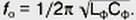
For the effective separation of the frequencies is important that the factor of the circuit had pretty noticeable amount, for example, would be at least 5. To meet this conditions stages transistors VT2, VT3 made under the scheme with a common base, for low input resistance Rin. Naturally, the filter itself is not must have a pronounced resonance. The required attenuation is entered into it from the side of the cascade transistor VT1, the output impedance which Rвых approximately equal to the resistance of the resistor R3. The output resistance value is selected depending on the acoustic design of the heads of the loudspeaker.
Suppose that in the process of making a sound is provided the addition of sound power of different frequency channels. This can happen if reproducing different frequency head speakers spaced apart and their axes of radiation are deployed relative to each other at an angle close to 90°. Then, as follows from the theory of calculation of the separation filters to equalize the total power output from the frequency resistance Rвых must be equal to: 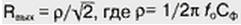 - the characteristic impedance of the circuit LфСф.
You can provide and the addition of the amplitudes of the sound waves, for example, placing reproducing different frequencies of the audio heads next to each other on one reflective Board. And heads should include anti-phase, as the crossover frequency fo of the currents flowing through the coil inductance and Lф capacitor SF, phase-shifted by 180°. The alignment of the total response in this case, when the output impedance Rвых=0,5 p.
In Fig. 2 shows the logarithmic amplitude-frequency characteristic of the filter channels. As can be seen from the figure, the steepness of recessions frequency response outside the bandwidth reaches -40 dB/Dec, which is the same value as the slope of the downs two-section RC filter. The effect of input resistance stages transistors VT2, VT3, Rin, and active resistance (rL) of the inductor Lф causes a decrease in the steepness of recessions at some distance from the frequency separation fо to -20 dB/Dec.
According to the author, it is desirable that the length of areas of AFC decay with the slope of -40 dB/Dec, was at least 10…15 dB along the axis of the coefficients transmission Uвых/Uвх. The main sound power will be divided between frequency channels and the further course of the AFC decay less than significant. The required form Frequency response is achieved when the quality factor of the circuit LфСфQ=p/(2Rвх+rL)>5, as indicated in the beginning of the article.
To set the separation filter by using a sound generator and AC voltmeter. Before setting in place of the resistor R3 should to install a resistor the resistance of which would be more characteristic loop impedance p. During the configuration process, you must ensure that transistor VT1 is sufficient for its normal operation voltage power. Now submitting to the input of the transistor VT1, the voltage of the sound generator and measuring with a voltmeter the voltage on the collector, see the quality factor of the resonant circuit is greater than 5, then determine the frequency resonance, that is, the crossover frequency fo, and if necessary, choose capacity condenser SF. After that, the values of fo and SF calculated characteristic the resistance of the p loop and calculate the required output impedance Rвых the first cascade. In conclusion, in place of the resistor R3 is solder a resistor a resistance equal to the calculated value Rвых.
At first glance it may seem that practically create LC filter can only with a sufficiently high crossover frequency, as desired coil with high inductance and low losses. This, however, is not. Explain the situation example.
The author was assembled Quad amplifier with these filters (Fig. 3).
The whole band of audible frequencies is first divided into a frequency of 850 Hz using the filter L1C4. Then the frequencies below 850 Hz divided by the filter L3C8 at a frequency of 220 Hz, while frequencies above 850 Hz filter L2C7 at a frequency of 3.2 kHz.
For inductors required magnetic circuits with suitable magnetic properties and possible large ratio of the area of the cross section of the magnetic circuit to the length the lines of force. These requirements are met by ferrite rings of small diameter, moreover, if necessary, the magnetic core can be composed of several rings. All coils are wound wire sew-2 0,12. As the magnetic core was used ring Khj,5 ferrite 1000 NN. Coil L1 wound on the two stuck together other rings and contains 520 turns, L2 - on the one ring and contains 400 turns, and L3 has four rings and consists of 520 turns.
The inductor of the low pass filter L3 were made as follows. Ferrite rings author of glued to each other so as to there are two of them equal to the height of the cylinder in contact along generatrix lines. The inner surface of the rings insulated paper. Winding produced a bundle of ten wires, which are then RASPAIL into a single winding. All adhesions to isolation and fixation of the relative position thus clamped between the two strips of adhesive tape.
In the filters applied to the capacitors km, KLS. For resistors and capacitors, select when configuring, a circuit Board provided space for installation of the two parts.
The interference from the mains transformer slightly exposed coil L3. Its fitting location and orientation I had to pick a minimum of interference.
The device worked fine when the voltage signal of 0.1 V. nonlinear Signs distortion due to the saturation of the magnetic cores of inductors not was observed. In conclusion, a few words about a complete audio system. In source soundtrack was used Phono "VEGA-206 stereo". In a four-band amplifier used power amplifiers from electrophone "Accord-stereo", and the speakers - spaced dynamic head HD-28, HD-35, HD-36 in different acoustic design. The sound installation of high purity and "transparency".
The capacitors in the separation filters is desirable to set metal film, for example, K73-16 or K73-17, since ceramic the capacitors at the required capacitance values are too large TKE.
Author: N. Boyko, Voronezh