In the article the author suggests a simple block of notch filters designed to work as part of a modular mixing console ("Radio", 2003, № 2, 3) sound system. This block allows to suppress spurious acoustic communication between the microphones and sound system without noticeable deterioration. As mentioned in the first article, a mutable set modules greatly expands the scope of small-sized remote control recording and sound reinforcement.
The biggest trouble providing sound reinforcement usually delivers appearance acoustic feedback ("feedback"), and combat is devoted to a large number publications. To suppress this effect, there are many devices that have their advantages and disadvantages. But it would be strange to recommend installation in simple Amateur remote [1] expensive digital filters or devices shift of the frequency spectrum. So focus on simpler versions.
It is believed that most acoustic "tie" occurs in the frequency range 125 Hz to 4 kHz, primarily at high frequencies chuvstvitelnosti microphones and speakers in their bad arrangement or the presence of sound reflections in the room. It is clear that for the generation breakdown in the system amplification is necessary to either reduce the gain or change the phase of the signal. By reducing the overall gain is lost the meaning of the sound. Can to apply a simple threshold and squelch to reduce gain only signals low, but this method is applicable if it is necessary to strengthen the voice only one person. But the sounds, the sources of which are further away from the microphone, are suppressed; this is not always valid. So, we need to reduce the gain of the signal only on the frequency that caused the "tie". This can to do with tunable notch filters. Not to make noticeable frequency distortion of the signal, band-stop filters must be narrow-band.
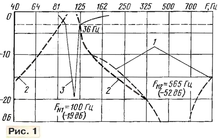
It is believed that "cut" the frequency bands of the signal spectrum width less than 0.1 octave's quite noticeable when listening to symphonic music, and speech it is permissible to increase this bandwidth to 0,2...0,3 octave. In practice with such task is successfully performed by one-third octave graphic equalizers, but it is very they are bulky. Much more convenient to use a parametric EQ or narrow-band tunable notch filters. Usually narrowband filters have a very large attenuation at the frequency settings, but from their amplitude-frequency characteristics (AFC) (curve 1 in Fig. 1) that reducing the gain on 4...5 dB occurs at a fairly wide band, and this already causing significant damage to the sound quality.

To resolve "ties" it is not necessary to introduce a large attenuation. So you could not use part of the frequency response of notch filter: if in the upper part of the frequency response of the filter to cut 20...30 dB, then and a strip of rejection will be very narrow and attenuation inserted by the device will remain quite sufficient. Easiest way will help achieve this goal if, instead of the filter use a tunable narrow-band amplifier and in the correct proportions to mix (sum) signal with the filter in opposite phase with the main signal. This "proportion" and will generate the desired part of the frequency response. Curve 2 in Fig. 1 shows the frequency response of the narrow-band amplifier tuned to the frequency of 100 Hz and the curve 3 corresponds to the response of the filter, taken at the output of the adder
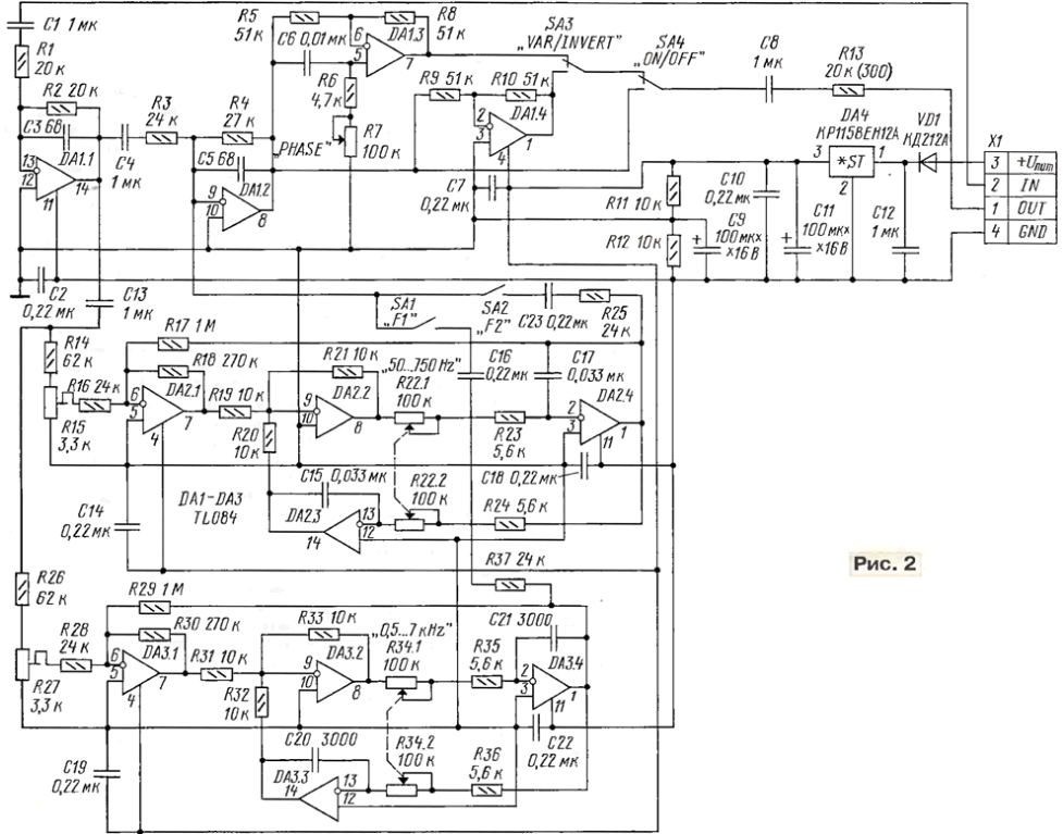
The module uses two of these filters (Fig. 2), collected on chips and DA2 DA3.

(click to enlarge)
Schema filters are identical and differ only in the values of capacitors C15, C17 and C20, C21. The first one you can rebuild in the frequency range 50...750 Hz, and the second in the band of 0.5-7 kHz. Optionally, change the quality and the gain of the bandpass amplifier [2]. These options determine following the ratio of the resistances of the resistors in the filters:
Q = R17/R18;
K = R17/R16.
You need to keep in mind that in a very narrow band cut frequency hard tune frequency sober and very easy to break the alignment. With a wide the bandwidth of the filter is noticeable by ear by frequency distortions. Trimmer resistors R15 and R27 (SDR - 19a) allow you to select which part of the AFC installing the proportion of the summation signal. Remember that when you rebuild frequency filtering the gain of the bandpass amplifier is somewhat different. Each of the filters include, if necessary, switches SA1, SA2. Sometimes there is a need to include both filters.
In the module there is further provided a tunable phase filter with OU DA1.3. His scheme is much simpler, but by changing the phase of a signal with high probability you can get the appearance of lasing at a different frequency. In practice eliminate high-frequency sober is better to choose a capacitor C6 with a capacity of 2200 pF, and the low-pass - to increase it to 0.01 UF. In addition, OU DA1.4, included as a phase inverter, you can use the toggle switch SA3 to change the phase in tract gain immediately by 180°. The rest of the OS (DA1.1, DA1.2) work respectively in the input and output stages. Oh the output stage at the same time performs the function of the adder.
When you enable the filter unit to the remote control after the input line with a signal directly to pin 13 DA1. Instead of elements C1, R1 set jumpers, because such a chain is, the output of the input line.
From the diagram it is seen that the toggle switches allow you to enable and disable any link. Phase filters will turn off the switch SA4 (at "OFF" mode "crawl"), and the toggle switches SA3 signal or the inversion of the phase of the signal, or for smooth adjustment of the phase change.
Module design filters of similar design modules, Amateur mixing console [1].

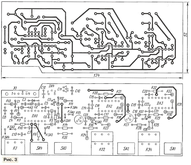
Drawing of the PCB is presented in Fig. 3, and the layout of the front panel of the module it is shown in Fig. 4.

In the design used TL084 chips (TL074, KUD). All capacitors filters shall be film, for example, K73-17
In the practice of such a block is almost always steadily allows to eliminate acoustic feedback. Adjustment of the filter must be done in the process check system health before the event and after that do not move the speakers and microphones. Incidentally, in the apparatus with much more complex digital filters, if you change the relative positions the microphone and speaker, for automatically reconfiguring the filters again.
Literature
Author: E. Kuznetsov, Moscow


