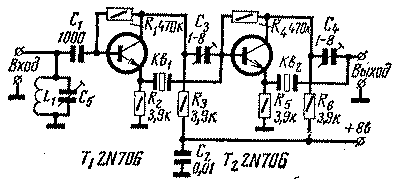
The Input terminal is connected to the anode of the mixer of the receiver through capacitor 1000 pF, the Output signal must be fed to the grid of the first if amplifier. The supply voltage can be obtained from a separate battery or from a power source of the receiver (through the divider resistors).

Frequency of the circuit L1C1 and quartz resonators Q1, Q2 should be equal to the intermediate frequency of the receiver. The exact match frequency oscillators due to their high figure of merit may the excitation filter, and therefore more appropriate to choose the frequency spacing of the order of 100 Hz.
In the transparency band filter has much less attenuation compared to EMF.
Filter setup is as simple as configuring circuit L1C5 and selection capacity of neutralizing capacitors CS.
Instead 2N706 transistors in this design you can apply the transistors KT315.
Author: W. Doty (WA4DID); Publication: N. Bolshakov, rf.atnn.ru


