Function generators are used by Amateur radio operators to check and establish a variety of electronic equipment. The author of the proposed article describes one variant of this generator that generates signals sawtooth and rectangular shapes.
As you know, function generators capable of providing an output signal triangular, sawtooth, rectangular, sinusoidal, and many other forms. However, such devices often used by professional experts developing sophisticated equipment. In practice for Amateur radio most cases sufficient, for example, to be able to get a signal triangular and rectangular shapes. The first of them will allow you to configure analog equipment range of 3H to identify (of course, if you have an oscilloscope) distortion type "step", the gain "above" or "below". Using a second it is possible to check and establish digital technology as well as control the dynamic characteristics of the analog equipment. The generator, providing such signals, is greatly simplified.
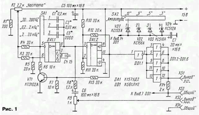
Diagram of the device shown in Fig. 1.

Actually the generator is made on the chip DA1 containing two operational amplifiers. On DA1.1 is assembled integrator, and DA1.2, a comparator (see Horowitz P., hill U. Art circuitry. - M.: Mir, 1998, p. 257). The frequency range of the generator from 20 Hz to 20 kHz is divided into three sub-band, which set the switch SA1, connects the integrator of one of the capacitors C1 - C3. In each of the frequency sub-bands generator change the variable resistor R2.
When charging customizados capacitor is formed by increasing time the voltage at the output of op-amp DA1.1 (pin 9). Once it reaches a certain value, the comparator changes the direction of integration. Customizado-schy the capacitor begins to discharge the voltage on the specified output to fall. In the result forms a triangular signal. Through the resistor R8 and the capacitor C6 it fed to variable resistor R9, and with its engine at the output socket XS3. The maximum voltage that can be set on the output variables resistor, reaches 1 V.
The output of the comparator (pin 13 OU DA1.2) are formed of rectangular oscillations forms that are received on the shaper is made on the chip DD1. This the chip allows the feeding to the inputs of the voltage
more voltage, so you can connect it directly to input 1 the output of op-amp DA1.2. The supply voltage is supplied via one of the Zener diodes VD1 - VD4, the output of logic elements DD1.2 - DD1.6 will be rectangular pulses with an amplitude of 3, 5, 9, 12 In depending on the situation the movable contact of the switch SA2.
Through the use of relatively powerful CMOS chip K561LN2, its output the current can reach 20...30 mA. Therefore, the device is suitable for setting up devices, collected on chips different series: K155, C, C, KR531, K555, C, KR1554 and many others.
When specified on the circuit component values, the frequency of the generated signal in Hertz is determined by the formula: Foutput=(40/S)·(UR2/u pit), where C is the capacity connected customizados capacitor, UF; UR2 - stress on the engine the variable resistor R2, V; u pit - voltage supply, V.
Since the OS eats a unipolar voltage, the value UR2 will be limited bottom. To used OS instance it was 1.45 In, with more a low voltage generator was not working. Therefore, to obtain a tenfold the overlap in frequency was chosen stable supply voltage of 15 V. However, the generator is operable at a lower voltage, but the overlap on the frequency for each sub-band is also smaller.
In the device, you can use any transistor series KT3102. Capacitors C1 W - PM-2, K71, but in a pinch, if you don't need high thermostability, - KD, KLS, K10-17, C4 - any type, C5 - C7 - C50-16, K50-35 or similar. Variable resistors - SP, SPO, JS4, constant - MLT, S2-33. Switches - of any type.
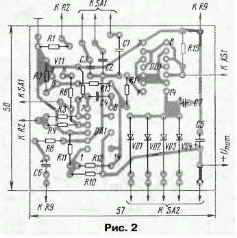
Most of the parts mounted on the circuit Board (Fig. 2) of one-sided foil fiberglass.

Charge installed in a suitable housing dimensions, and fastened on the housing switches, sockets and variable resistors. The resistor R2, it is desirable to provide scale and to put on her values generated frequencies for each sub-band.
When establishing the unit initially choose the resistor R1 such resistance, to the left (the scheme), the position of the slider of the resistor R2 steady the operation of the generator to the lowest frequency of 20 Hz (movable contact switch SA1 is in the "20...200 Hz"). Frequency sub-bands set selection of capacitors C1 - C3, and the maximum amplitude triangular voltage selection resistor R8.
Operating frequency of the generator is limited by the speed of the OS and used is 40...50 kHz. If the receipt of such frequencies is necessary, you should add another customizados capacitor, apply the switch on four position and install the other sub-bands, for example, 4 to 40 Hz 40...400 Hz 0,4...4 kHz, 4...40 kHz.
Author: I. Nechaev


