In the development and research of electronic equipment in the laboratory is one of the most important components of the measuring complex is a universal source of test signals. Functional generator operating in the range of sound frequencies, was developed on the basis of microcontroller. Based on the oscillator circuit described in Radiohome, 2000, № 5, p. 79.
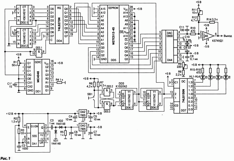
The analysis of this scheme it was identified a significant disadvantage. Due to the fact that the counter is made of two functional elements, the logic levels of address the conclusions are set simultaneously, that will lead to the emergence of high frequency emissions at the output of the generator. The developed device is devoid of these shortcomings. Generated form output signal (sawtooth, triangle, sine, square wave) is programmed in flash memory. The generator used the firmware provided in Radiohome, 2000, № 5, p. 79. Schematic diagram of the function generator shown in Fig. 1.
Main technical parameters
The range of generated frequencies, Hz 0...30000 Frequency response, dB <0,3 The amplitude of the output voltage, In 4 The number of stages of the output signal 128+128 
On the chip 4046 MS (DD1) assembled the master oscillator, which frequency tuning in the range 0...4 MHz. Variable multi-pass resistor R1 is used to adjust the frequency. On the chip IE (DD2) assembled an address counter whose output signals are formed ("dial address") entering the address inputs of EPROM Winbond W27C512 (DD4). In this IC chip flash memory is programmed in the form of output signals. From outputs of EPROM signals are transferred to the DAC DAC0800 (DA4), the output of which the signal enters the high-speed operational amplifier CUD (DA5). Button SB1 is used to select the output signal format. On the elements of the chip AS (DD3.2, DD3.3) assembled host debounce the button SB1. From outputs 5 and 9, which also receives signals from outputs of EPROM, a signal is sent to the decoder chip SN74LS156N (DD7). Its outputs are removed the data about the selected signal, which is displayed one of the LEDs. For indication of the selected output signal format is compiled node on the D-trigger circuit TM (DD6), the input of which receives pulses that occur when the switch of a button.
The device is powered from the unregulated source voltage of + 12 V, which comes on the integral timer and stabilizer DA1 positive voltage DA2. On the timer DA1 implemented multivibrator, the output of which rectangular pulses are removed. They are straight and to the input of the negative voltage stabilizer DA3. The voltage taken from its outputs, is used to power the generator. When you configure a device, you first need a selection of C1 set the frequency of about 4 MHz at pin 4 of the chip DD1, then the resistor R11 in the mode of generation of the sine wave by controlling the output signal of the oscilloscope, set the symmetry of the signal relative to the common wire. Maximum output frequency of the generator is determined mainly by the performance EPROM, which for the chip Winbond W27C512 is approximately 4 MHz, so the maximum output frequency: 4 MHz/128 steps = 30 kHz. Measured harmonic distortion of a sinusoidal signal are 0,0076 % at a frequency of 1 kHz.
This generator was designed to work together with the digital oscilloscope, which displays the frequency of the input signal, so additional indication of the frequency of the output signal is not provided. Devices, microcontrollers, quite promising. For example, the proposed generator can increase the frequency due to the application of the master oscillator with greater frequency. Also due to the increasing capacity of flash memory you can increase the sampling rate. The generator can be connected to a personal computer with the ability to programmatically change the shape of the output signal by changing the firmware flash memory. Resistor R1 - SP5-44-1 or other multi-turn, R9, R11 - Spssa or other small. The software for this design can be found on the journal's website at the address www.dian.ru.
Authors: Andrey Bells, Andrey Donovich, Andrey Babayev, Tambov; Publication: www.cxem.net


