


")

It is considered that the most stable Besarabia oscillators - tube. However, when the corresponding circuit of the oscillator and full account of the specifics of the transistor in the self-refresh modes on HF can be obtained the stability of the scheme, not much different from the circuits for the lamps.
Applied by the author of the scheme (see figure) is an oscillator with capacitive coupling, which in a structural sense, the most rational.
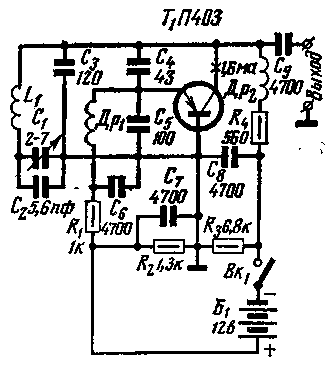
A crucial part of the contour generator is a coil L1. It is made of hot-wound on a ceramic frame with a diameter of 20 mm and is enclosed in a screen of thin copper (can use aluminum). The wire is silver plated with a diameter of 0.64 mm, the winding pitch is 1.5 mm, the number of turns of 10.5. The coil has a quality factor of 300. This reduces the connection of the transistor circuit, resulting in a reduction of the influence of the parameters of the oscillating circuit on the steepness of the characteristics of the transistor, and this makes the stability of the generator is more uniform over the range.
The RF chokes wound on pre-cleaned skeletons resistors sun to 1.0. DR1 contains 130, and DP2 - 55 turns of wire PELSHO of 0.12.
Variable capacitor C1 type KVM. Fixed capacitors, it is desirable to use heat-stable (from HF ceramics class III, type A) with a tolerance of capacitance ±5%. C2 - C5 - type CT or CD groups stability m M47 (blue color), P33, P (blue). S6 - S8 - type CD, type SWДС. Structurally, all of the master oscillator is performed in a hermetically closed block.
When you configure govern the resistance of resistors R1 and R2 to determine the optimal bias voltage the Uэб=0.2. With airtight construction thermal regime occurs in 20 - 35 minutes.
The destabilizing effect of the power circuits and the parasitic oscillations are virtually eliminated with the correct calculation of parameters R4, R1, and capacitors in the feedback circuit.
The power consumed from the power source - 40 mW; output power is 0.6 mW.
Author: A. Yashin (UA3-160-86), head UW3KAK, Tula; Publication: N. Bolshakov, rf.atnn.ru