To build antennas using a measuring bridge, you need a source stable RF signal operating in the Amateur bands and having an output power is not less than 100 mW. To use the transceiver is not always convenient, especially if measurements need to be made on the roof (directly about the antenna).
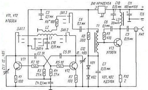
Diagram of the generator shown in the figure.

The basis was taken the scheme, published in the magazine "Radio" (1999), No. 5, p. 59). The generator covers the frequency range from 1.4 MHz to 30 MHz in three ranges: 1,4...to 3.2 MHz. 3,2...8,0 MHz 8,0 30,0...MHz. In the first sub-band of his output power (measured at 50 Ohm load) of not less than 400 mW in the second range not less than 300 mW, in the third range is from 150 mW to 30,0 MHz to 200 mW at 8 MHz. When connecting the antenna to the care of the oscillator frequency is 5 kHz the first range is not more than 15 kHz on the second and not more than 30 kHz on the third. It allows the use of this oscillator for configuration narrowband antennas, using a simple mechanical scale in its design, and be confident in true her testimony.
As can be seen from the figure, the circuit consists of specifying generator on transistors VT1, VT2 and linear power amplifier for the VT3 transistor. High performance master oscillator were obtained transistors type CTA. The desired range of the generator is chosen the switch SA1. Switching ranges the diagram shows a simplistic, only for one band to avoid cluttering the figure. The master oscillator powered by the stabilized voltage of +5 V. This voltage is applied in the base circuit of the transistor VT3 power amplifier. Such a construction of the power scheme able to keep a stable frequency of oscillation starting voltage of +8 V to the maximum value of the voltage of the power generator +15 V. the Chip A1 is used without a heat sink. The generator is assembled in body size HH 100 mm from a two-sided foil fiberglass. For frequency stability its design should be, if possible, more rigid. Generator installation made in hinged manner (on the patch), on the back of the device.
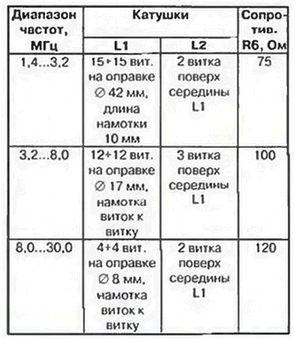
Constructive data of the coils, and the initial value of the resistance R6 to each of the subbands shown in the table.

All coils are wound with wire Sew-0.5 mm. 2 of the Transformer T1 is wound on a ferrite ring cores brand N size CHH mm. Its winding consists of 2x10 turns of twist of wire sew-2 0.3 mm. Choke L3 standard DM and 0.2. As C1 used variable capacitor with air dielectric from the old receiver and with double Vernier slowdown. The switch SA1 - ceramic disk type IAP SPAN. High-frequency connector - SR50-FW. Setup generator is not complex. If possible, the transistors VT1 and VT2 must be used with the same coefficient of transmission of the base current.
Oscilloscope or RF voltmeter you must ensure the equality of the amplitudes of the high frequency voltage the collectors of these transistors. If the levels of the signals differ by more than 30%, it is desirable to choose the transistors VT1 and VT2. If necessary, choose resistors R1 and R7, R2 and R5, achieving a sinusoidal output signal at all ranges. The selection of resistor R8 sets the collector current of the transistor VT3 within 100...150 mA. This transistor is mounted on aluminum the heat sink size 40x40x4 mm. Resistor R6 are selected independently for each range. The greater the resistance of this resistor, the higher the stability the frequency and the lower the power output of the generator. The boundaries of the ranges of work generator put compression-stretching of the outermost turns of the coil L1. She needs to be performed symmetrically.
Powered generator from an external source voltage of +12 V. It can be dry cells and batteries. Consumed by the generator current is about 200 mA.
Author: I. Grigorov (RK3ZK)


