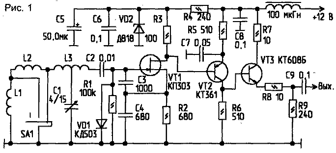
Feature of the scheme is the simplicity, the lack of scarce parts, a convenient overlap of the ranges when using just one biscuit, slight frequency drift.
When using this circuit at higher frequencies (good job observed up to frequencies of 30 MHz) as the transistor VT2 need to use CT, VT3 - CT, VT1 - K.
Instead of the resistor R3 when the frequency multiplication can be placed on the contour to the desired harmonic.
At these values of the GPA covers the frequency 7,600 7,500...MHz; 4,00...4,200 MHz and 2,330 2,430...MHz, the dissipation from the coil L3 is done from the middle. C1 you can use blocks from УSW broadcast receivers. With the aim of producing coils L1, L2, L3, you can use resistors MLT-2 after removing the conductive layer. Adjustment of the inductance in this case it is convenient to make the inclusion of additional coils on MLT 0.25-mounted switch ranges.
Temperature stability is selected by the change of TKE capacitors C3, C4 (CSR, group G). On the bands 160 and 80 m, the level of harmonics can be large, if necessary, to reduce the level of harmonics is possible to connect a shunt resistor to the right output L2.
Author: V. Zhuravsky (ER4OT), Moldova, Soroka; Publication: N. Bolshakov, rf.atnn.ru


