


")

The magazine "Radio" repeatedly published descriptions of various instruments and devices that use the chip - timer CREW. In most he connected in the circuit, close to the model, designed to generate rectangular pulses.
The author of this article in order to broaden the scope of the timer, offers the readers some new and little-known schemes of generators CREW.
First, consider a simple generator, assembled by well-known the diagram (Fig. 1). The generator produces rectangular pulses with a duty cycle, equal to two. The period of oscillation is associated with the values of resistor R1 and capacitor C1 ratio T=1,4R1.C1.
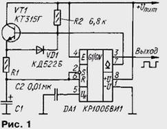
At power on, the capacitor C1 begins to charge through resistor R1 and open the transistor VT1. When the voltage on the capacitor reaches 2Uпит/3, the output voltage (pin 3) of timer DA1 is reduced to zero and simultaneously with this will open the internal transistor of the timer by connecting its output with open the collector (pin 7) to GND (hereinafter, for brevity, the output from open collector will be called "output OK"). Transistor VT1 in this case will close as the voltage on the base will be practically zero. The capacitor now discharges through the resistor R1 and the diode VD1. When reducing the voltage on the capacitor to a voltage u n and m/3 internal transistor timer closes and the cycle of operation of the generator again.
Thus, the capacitor C1 charges and discharges through the same the resistor R1, which determines the time constant of charging and discharging. So the duty cycle of the output pulses very close to the two. More accurate duty cycle pulses can be set by selection of resistor R2.
In Fig. 2 shows a diagram of another generator of rectangular pulses of the form "meander", the repetition rate can be adjusted by the variable resistor R2, and the duty cycle remains constant.
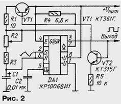
Immediately after power-on timer output sets the voltage high level, since the capacitor C1 is not yet charged, and the voltage at the input S chips below the threshold level (equal 2Uпит/3). Collector current open transistor VT2 opens the transistor VT1, therefore, the capacitor C1 begins charged via the resistors R1-R3. When the voltage on the capacitor reaches 2Uпит/3, the trigger timer will be switched to the zero state. Both transistors closed, but will open an internal transistor of the timer by connecting the common wire exit with OK. The capacitor C1 now discharges through resistors R2 and R3.
The resistor R1 is to limit the current of the transistor VT1 during timer switching. To generate pulses with a duty cycle that is most close to two, it is necessary that the resistance of the resistor R1 was significantly less than that of resistor R3. The oscillation period can roughly calculate, using the expression T=1,4C1(R2 + R3).
The generator, the circuit of which is shown in Fig. 3, also produces rectangular oscillations of adjustable frequency with a constant duty ratio equal to two. But in unlike the options described above, the voltage on the capacitor in the generator changes not exponentially, but linearly.
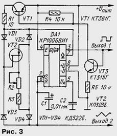
Generator works similarly to the previous one, except that the charging and discharge current of the capacitor generates a current source FET VT2. Diode bridge VD1 - VD4 rectifies the voltage applied to the transistor VT1. The period of oscillation is associated with the values of timing elements ratio T=2C1.U pit/(3I), where I is the current produced by the source.
The minimum voltage at which the possible stable operation of the device, as well 9 V. With a smaller value capacitor voltage may not reach threshold 2Uпит/3 (or will run out before u pit/3).
Since the capacitor C1 can be removed vibrations of triangular shape, their amplitude is equal U pit/3. The load capacity of output 2 is very small, so it is advisable to include load via intermediate repeater voltage of a field effect transistor, assembled in one of the schemes in Fig. 4, or by operational amplifier.
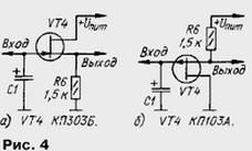
The voltage on the capacitor is between u n and m/3 and 2Uпит/3, so there is a possibility of a single supply operational amplifier. So, I were tested OS CRUD, CRUD designed for a bipolar power 2x15 V. It turned out that they normally operate in this mode even when unipolar a voltage of 9 V. At lower voltage can be applied Quad opamps CUA or CUB. They are efficient at reducing the supply voltage to 5 V.
In addition to the load, the negative effects in the form of oscillations have also input current timer, leakage current of the capacitor C1 and the reverse current of the diodes of the bridge. If the source of the transistor VT1 generates a too low current, the voltage at the capacitor will cease to be linear. For this reason, it is desirable to select diode rectifier bridge with a minimum reverse current. Most low-power silicon diodes reverse current under normal conditions does not exceed 1, therefore, the current source can be reduced to 1 μa or less. In this case the total resistance of the resistors R2 and R3 should be close to 1…2 MW.
Field-effect transistor VT2 (Fig.3) with an n-channel will replace the p-channel. With this replacing the polarity of the diodes VD1-VD4 bridge must be changed to return.
The generator of rectangular and triangular voltages can be build completely on bipolar transistors, as shown in Fig. 5. On the VT3 transistor is assembled a current source that generates a charging and discharge current of the capacitor C1. Transistors VT2 and VT4 form a "current mirror". The purpose transistors VT5 VT1 and clear from the description of previous versions of the generator.
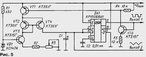
When the high voltage level at the output of the timer DA1 transistors VT5 VT1 and open. The capacitor C1 is charged through the transistors VT1 and VT4. "Current mirror" transistors VT2 and VT4 provides the current through the capacitor, equal to the current generated by the source of transistor VT3.
When a low level at the output of timer transistors VT1, VT2, VT4 and VT5 are closed therefore, the capacitor discharges through the collector junction of transistor VT4. Current discharge of the capacitor also sets the current source transistor VT3.
If you implement this generator must be borne in mind that to implement all advantages used schematics transistors "current mirror" must be a General Assembly on the crystal, otherwise it can give significant current error (10 times or more) and the strong dependence of the current on temperature.
The triangular voltage is removed from the capacitor C1 via the repeater on a field-effect transistor or op amp.
If there is a need for frequency modulation of the generated oscillations, the Zener diode VD1 and the resistor R1 is eliminated and the modulating voltage is served on the base of transistor VT3.
On the timer CREW also possible to construct the generators of the sawtooth oscillations. Scheme of one of these generators is shown in Fig. 6. When the output of the timer DA1 is present the voltage is high, capacitor C1 charges relatively slowly from the current source FET VT1. Once the voltage on the capacitor reaches the level 2Uпит/3, high level voltage at the output of the timer will change to low and the capacitor is quickly discharged through outdoor internal transistor circuits.
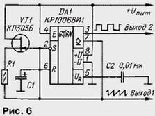
The frequency of oscillation determine the current I of the source transistor VT1 and capacity capacitor C1. The period of oscillation of the generator is equal to T=C1.U pit/(3I)
The generator according to the scheme of Fig. 5 can provide voltage and ramp - it's enough to exit with OK timer (vyv. 7) connect via contacts toggle switch with inputs R and S. the Sawtooth oscillations is removed from the outlet 2. So by the way, the generator becomes this tri-function.
Author: A. Shitov, Ivanovo, Moscow region.