


")

The proposed construction of a high-frequency power meter is developed on the basis two of the devices described in [1, 2], where the possibility of applying miniature incandescent lamps in the measuring apparatus.
In addition to the simplicity and availability of the used sensor elements, the author were attracted by the fact that the setup is similar to the broadband device is not requires high frequency measurements. You must have a digital-only three - or four-digit multimeter. All the measurements were carried out at a constant current.
The main difference of the proposed design of the wattmeter is that the measuring bridge is connected to the sensor-Converter for lamps the filament is balanced automatically in the process.
Wattmeter, which is discussed below, can be used as a stable the noise generator with the agreed output impedance of 50 Ohms. Since the device has a host of automatic stabilization of the resistance (ACC) sensor, temperature the filament is also stabilized with high precision. In terms of noise level you can indirectly judge the working frequency band of the device. Noises lamps extend all the way to 1 GHz. and the decline begins at frequencies of 600…700 MHz, which corresponds to data given in [1, 2]. About the noise generators and the measurements with them help can be found in [3, 4].
During experiments it was found that the bulb was very sensitive to mechanical stress. In practice, this means that the device should be protected from vibrations, otherwise the parameters of the Converter can abruptly to change. This is apparently due to the displacement of the thread plugs and change the mode of heat transfer. The most stable level, as the test showed, is the one to which the sensor goes out after switching on power. Since the node ACC works very stable, and the transition to another level RL is easily located by the dial gauge as a shift "from scratch". If you want accurate measurement, you need to switch off and then switch on the supply voltage. The stability of the sensor, not related to mechanical effects, rather high: during the day the device is not detected zero offset and limit (on dial gauge), which isn't the case, for example, industrial millivoltmeter VZ-48.
Fundamentals of applied method of measuring RF power is contained in [1, 2]. Denote in the text correspond to the original articles. The total power heating filament lamps,
RL = Next + Rsem. ( 1)
where Next - high-frequency power. Rsam - replacement DC power [2].
Convert the expression (1):
Next = RL - Rsum = (Uл2 - Uзам2)/R = (2Uл·ΔU-ΔU2)/R. (2)
where ΔU = Il - Uзам; RL = Uл2/R; Rsum = Uзам2/R: R = 200 Ohm (or 50 Ohm to sensor with parallel connection of lamps, see below).
From the expression (2) implies that the value of the RF power at the input of the sensor is function of the voltage differences ΔU = Il - Uзам. This voltage difference (if the condition of bridge balance) measures the power meter. Formula (2) can be represented in normalized form:
Next/RL = 2ΔU/Il - (ΔU/Yl)2 (3)
The type of function (3) is shown in Fig. 1. Using the graph or on it analytical expression (3). for microammeter to draw non-linear the scale values and Next/RL. which is the same for any sensor. The calculation of the measured RF power is produced by multiplying the readings by the value of RL specific sensor (manufactured sample had a value of RL = 120 mW). If this scale pointer instrument shows the value of "0.75". measured power on the equal sign:
Next = 0.75 PC = 0.75-120 = 90 mW.
From the graph we see: if for measurements use only the initial portion range RL, the nonlinearity of the scale will be less. Therefore, in the manufactured sample the power meter uses two linear scale of the microammeter. corresponding to the two the limits of 40 and 100 mW. For a specific sensor with RL = 120 mW position the upper limits of these ranges are shown in Fig. 1. Nonlinear and linear scale paired in two points (zero and maximum). At other points of the device of understates testimony to the power measured.
Since most RF measurements is as simple as configuring the maximum (minimum) value of voltage or power, analog display most comfortable, and the specified accuracy of the scales is not a significant disadvantage. Except also stored in the device the ability to measure the exact value of the power external digital voltmeter [2].
Schematic diagram of the device depicted in Fig. 2. Voltage stabilizer DA1, DA3 included in the model scheme. The capacitors C4 and C6 reduce the pulsation level output voltage. Integral stabilizer creates a negative DA2 the offset of -2.5 V, which is used to power the op amp. The stabilizer performs DA4 the source function reference voltage 2.5 V (ION).
(click to enlarge)
The node ACC performed at the OS DA7 and the transistor VT1. The principle of operation of this node similar to the ordinary compensation of the voltage regulator, but instead the Zener installed another nonlinear element is an incandescent lamp. Balance the bridge is supported with high precision (up to 10…20mkv) change its supply voltage (R7 - R10 and lamps sensor). The resistors of the bridge matched with an accuracy of ±0,1%.
Since the bridge is balanced, when the sensor is consistent with the connection of the lamps (Fig. 2) the equation:
Rd = R9 + R10 = 200 Ohms,
where Rd is the resistance of the sensor.
Digital 3.5-bit the device is not able to measure resistance with a specified accuracy, but it can be calibrated using precision resistors (for example. C5-5V) with a tolerance of 0.05 to 0.1%. Since the elements of the bridge are heated in the process, resistors MLT is not recommended due to the large the values of TCS±(500… 1200)-10-6 1/°C [6]. It is important that the resistors R7. R8 differed by no more than ±0.1%, and the value can be set in the range 47…75 Ohm. Shown in the diagram power resistors included in the shoulders the measuring bridge, it is not recommended to reduce.
Immediately after powering on the unit to start ACC resistor R6 creates small initial current flowing through the bridge, so the maximum measured specific sensor power somewhat less than RL.
With high-frequency connector XW1 also remove noise voltage wideband frequencies.
For normal operation of the node ACC lamp must operate in the mode, when the thread lights up weakly or not lit at all. Under bright illumination voltage dependence on the lamp from protekayushih current is close to linear, and this linear plot ACC unhealthy.
The maximum power of the sensors used by the meter, does not exceed 250 mW. Here we consider only sensors with an input impedance of 50 Ohms. but it is possible to use sensors with a resistance of 75 Ohms [2]. The resistors the bridge in this case: R9 = 225 Ohms. R10 = 75 Ohm. The power sensors with the same copies of the lamps will increase about two times, so you have to increase the supply voltage of the bridge.
Sensor type "a" is described in detail in [1, 2]. When it's working DC resistance is 200 Ohms. and from the RF input - 50 Ohm Lamp for such a sensor must pick up in pairs, so that in the on state the voltage drop on both lamps were approximately equal. Checked it several copies of the lamps, it is easy to verify that this condition is often not met, even when the resistance of the lamp in the cold state the same. If we assume that the input impedance must be 50 Ohms ±0.25 %. this if the voltage on the lamps connected to the power meter, differ by not more than 15%. The sample sensor, which test the operation of the device, had the following parameters: Il = 4,906 In (RL = 120 mW). Un1= 2.6 V. Un2= 2,306 In (the difference of the voltages at the lamps about 12 %).
In Fig. 2 for CI. S2 sensor "A" specified denomination of 0.44 µf that enables to reduce the lower limit of the frequency range to 1… 1.5 MHz. To reduce the inductance of the input circuit uses two parallel-connected CHIP capacitor 0.22 UF. When specified in [1, 2] the values of capacitors (0.047 UF) measurement accuracy of about 1% can be achieved only in the limit of the frequency range not lower than 15 MHz, 150 kHz.
Unlike described in [2]. offer wattmeter allows you to use two type sensors, in which the lamps are connected in series (sensor type "a") or parallel (sensor type "B").
Connected to the sensor device type "B" jumper at pins 1 and 4 of the connector the sensor closes the resistor R9 of the bridge, so Rd = R10 = 50 Ohms. For sensors that type selection of a particular pair of lamps are not needed. To obtain the desired value of the ABL. the sensor can be used from one to four lamps, and they can be various type. To extend its frequency range down increase the inductance of the inductor should not lead to an increase in its active resistance (preferably not more than 0.25 Ohms. i.e. 0.5 % of 50 Ohms). The throttle it is necessary to wind the wire diameter of 0.3…0.4 mm to get coil inductance of 50 µh with the size of the resistor MLT-1. With this inductance the lower bound of the frequency range sensor "B" is equal to 16 MHz contrast sensor inna "A", which is quite accurate already at a frequency of 1 MHz.
On chips DA6. DA7 and LEDs HL1. HL2 made a comparator. It the purpose is to display the balance of the measuring bridge. When he balanced, both LEDs are extinguished. When specified on the diagram the values of resistors R29 and R31 deadband comparator is approximately ±60…90 mV. If the RF power at the input of the sensor is equal to the maximum valid value RL (actually slightly less). ACC is unable to balance the bridge, and one of the LEDs HL1. HL2 is included, showing that the measurement impossible.
The inertia of the incandescent lamps allows to see the regulatory process (duration 1…2). As a result, the indicator has another positive function It allows you to define small and fast changes in the amplitude of the RF the signal at the input of the device. It is known that these fluctuations of the amplitude characteristic for unstable amplifying cascades or generators, which tend to delays and spurious frequencies. For example, when checking the power meter from generator G4-117 was found that at frequencies above 8 MHz and the output level signal greater than 2 In (50 Ohm load) the generator does not work internal stabilizer amplitude of the output of signup.
The node display of the device is performed at the OS DA4. DA5. the micro-ammeter PA1. Variables resistors R19 (corrector "zero") and R24. R26 and R25, R27 (corrector "range") allow you to easily configure the power meter to work with any sensors that have RL < 220 mW. With a wide range of adjustment it is best to use multi-turn wire wound resistors. Therefore, to adjust the "zero" in the device set variable resistor type SP5-35B with high-resolution electrical ability [6]. Additional correction of zero when switching to another range measurements are usually not required. Adjustment of zero and span is not affected each other. The presence of the diode bridge caused by the fact that power - positive value. In this embodiment, the inclusion of the microammeter his arrow does not pass through zero.
Most of the elements of the device is placed on the same Board, and those that heat up during operation of the wattmeter (DAI, DA2. VT1. R7-R10). have thermal contact with aluminum back panel of the device. To configure the device better in a closed body. The design must provide access to all adjustment elements.
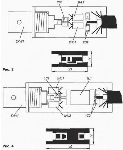
Design of sensors and drawings of printed-circuit boards shown in Fig. 3, 4. Foil the reverse side of the PCB is fully preserved. High-frequency connector and the braided cable probailout on both sides of the Board. To minimize its own inductance sensors used for surface condensers installation (with a capacity of 0.22 and 0.022 UF in two pieces, connected in parallel). Case high-frequency connector soldered to the foil on both sides of the Board.
The wattmeter used precision wire wound resistors S5-5 V 1 W impedance of 100 Ohms with a tolerance of ±0.1 % (TKS ±50·10-6 1/°C). As R7, R8, R10 is established by two parallel connected resistor and R9 is formed series-parallel inclusion of the three. Acceptable use and other precision resistors, for example, C2-29V, C2-14. Resistors R24 - R26 - trimpot. wire SP5-2, SP5-3. Socket XS1 sensor - ONTS-SH-4-5/16-R (SG-5). high-frequency connectors XW1 - SR-50-F. Power connector - pin, socket DJK-03B (2.4/5.5 mm).
Instead most KDE you can use any diodes, for example, series D9, D, CD. KD521. Microammeter - M24. M265 with the current total deviation of 50 - 500 mA.
CREE can replace imported low-power analog - LM317LZ, and CU IN - TL431.
Adjustment of wattmeter produce assembled in 10-15 minutes after inclusion.
First contacts 2, 3 of the connector HR connect any pair of lamps SMN-60. connected in series and to terminals "A" and "B" - digital voltmeter, which included in lower limit of measurement (200 mV). Rotating the trimmer R15, achieve zero voltmeter.
After balancing the measuring bridge configures a comparator. The Resistor R21 (or R23 depending on the initial bias Oh DA8. DA9) temporarily replace (the housing will have access to) a variable resistor 100 ohms. Changing the resistance of the resistor, making the state both LEDs will be repaid. Then replace the variable resistor with constant close to that found resistance. The con ly similar adjustments are offset by a relatively narrow, therefore, prior to installation in the fee it is advisable to check the value of the initial offset all opamps Chips with minimal offset to use as the DA8. DA9. For other circuits the magnitude of initial displacement is not as important as their modes of operation can be adjusted by respective variable resistors.
After configuring the comparator need to make sure its dead zone is ±60…90 mV. Resistor R15 valid in a small range to unbalance the bridge, and connected by a digital voltmeter to determine the voltage of the error at which the LEDs are turned on. It is desirable that deadband comparator was symmetrical (relative to the point the balance of the bridge). For expand, you can increase the resistance of the resistor R29.
After setting the comparator, the resistor R15 finally balance the measuring bridge. Using the resistor R19, you should check that randomly selected lamps set the zero reading of the microammeter RA1.
By performing these operations, included on the device you pair of lamps for sensor mechanical stability and difference voltages. Digital voltmeter need switch to socket "0", "B". It will show voltage Un, which easily calculate RL. The top point of the "range of 100 mW and 40 mW" can set by calculation, since for a given value of RP is known, what the voltage display digital voltmeter at specified points (Uзам). The entry signal the sensor can be submitted from any generator with a frequency above 2…3 MHz and weekends voltage less than 2.5 V (50 Ohm load). The level of the signal generator govern according to the testimony of a digital voltmeter. the voltmeter showed estimated value of the Uзам, after which the adjustment of the resistor R24 (R25) set arrow microammeter on the last scale division.
To power the device, you can use any source with an output voltage 15…24 V the inflow of 150…200 mA. If you use a low-power network "adapter" should be make sure that the lower limit of the ripple of the input voltage, at least 2.5 V greater than 12 V.
Direct verification of the characteristics of the fabricated device could not be held due to the lack of appropriate instruments. So on the inspection frequency properties sensor at frequencies of hundreds of megahertz. Available the author had only a digital multimeter DT930F+ (accuracy class 0.05 when measuring DC voltage and 0.5 when measuring resistance, RMS AC voltage up to 400 Hz [5]), low frequency generator GP-117 (to 10 MHz), and millivoltmeter VZ-48 (class precision 2.5 V bandwidth 45 Hz… 10 MHz).
Checking several points on the scale (the testing was carried out on the digital voltmeter, and not on the scale of the microammeter) at a frequency of 5 MHz showed that the wattmeter works more accurate and more stable than the OT-48! Well, this was on the millivoltmeter the rear wall of the control socket to which you can connect an external (digital) voltmeter. Under the assumption that VZ-48 has no frequency error in the average part of the working frequency range, the calibration was carried out three points of tension at a frequency of 400 Hz. for available digital voltmeter class 0.5.
After that, the generator was rebuilt at a frequency of 5 MHz and a digital voltmeter (and not on the analog scale OT-48) have been restored previously measured values the voltage on the sensor input. According to the testimony OT-48 power was calculated on the entrance from the relation RL = U2/50. and the power that was shown by the meter, was calculated by the formula (2).
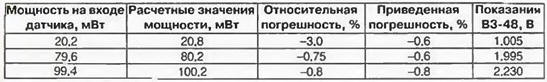
The results of these measurements are shown in the table. Particularly impressive is that in the obtained values of the errors is clearly visible the presence of systematic errors [7, 8], which means that the parameters of the power meter can be even better!
The sensors can be used for different thermistors - both positive and a negative TCR. In order for the node ACC worked with thermistors with negative TCR (incandescent lamps have a positive TCR), in the circuit of the device provided jumper (shown dash-dotted line) that you want to move to a position between contacts 1 and 4, 2 and 3.
To test the functionality of the SCA, with the sensor having a negative TCR, was used thermistor ICIT-16 busenkova type with a nominal impedance A 5.1 kω [6] when the connection of the sensor "B". Despite its large size the source resistance, the voltage of 10 V was enough to warm-up miniature thermistor and balancing of the bridge. But since the working the temperature of the thermistor substantially lower than for the filament, and insulation worse, this sensor works more like measuring temperature and the stability of the zero is very low. The value of RL = 102 mW.
For those wishing to experiment with different sensors you can give some General advice. The source resistance of the thermistor (for any sign of TCS) you need to choose such that the resistance of the heated thermistor (or the combination of several resistors) equal to 50 Ohms. achieved the maximum possible temperature of heating. For example, thermistors ST1 -18. ST1 -19 busenkova type operable to +300°C [6]. In this design the sensor should be taken passive thermal stabilization and thermal insulation the thermistor.
Thermistors with a negative TCR at the moment of inclusion can have too great resistance, so in order to create conditions of self-heating can to require a significant increase in the supply voltage. When using the posistors nutritional problems will not arise.
Except SMN-60. you can use other types of miniature incandescent lamps, the parameters are given in [1, 2]. Easy to get converters with the value of RL from units up to hundreds of milliwatts. Measurement greater power of the RF signal carried out through the concerted attenuators. With the calculation of attenuators can be found in [9,10].
Literature
Author: O. Fedorov, Moscow