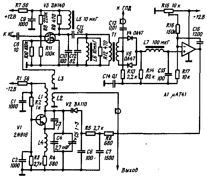
The local oscillators phase-locked loop frequency (PLL) allows a fairly simple means to solve the problem create a highly stable signal source of variable frequency for sports УSW equipment. Diagram of the local oscillator is given figure. He had been employed at the receiver, the band 144 - 146 MHz with one frequency conversion and intermediate frequency of 10.7 MHz.
The local oscillator consists of the controlled oscillator transistor V1. reference crystal oscillator (KG) and highly stable generator of a smooth range (GPA), mixer transistor V3, phase detector diodes V1, V5 and the DC amplifier on the chip A1. Elements quartz and highly stable generator of a smooth range the figure does not shown.

A controllable oscillator generates a signal changing when applying the control voltage to the varicap V2, within 154,7 - 156.7 MHz. The signal from this oscillator is fed to one of gates of the transistor V3 and via buffer amp at first the receiver mixer. To the second gate field-effect transistor with the reference oscillator signal frequency of 161 MHz. The difference signal, the frequency of which may lie within A 4.3-6.3 MHz is allocated to the bandpass filter L5C10C11L6C12. This signal with a high frequency voltage from the generator smooth the range is supplied to the phase detector. The error signal that has passed through a lowpass filter L7C15 and enhanced operational amplifier A1 is supplied to the varicap V2 in a controlled generator.
To extend the bandwidth of a bandpass filter L5C10C11L6C12 to 2 MHz its contours are shunted by resistors R9 and R12.
The frequency stability of the output signal of the local oscillator with PLL is determined mainly by the stability of the oscillator smooth range, which at low frequencies (in this case, a 4.3-6.3 MHz) you can get very high.
Note
Transistor V1 can be any high frequency with a cutoff frequency of generation of at least 300 MHz (for example, CTA). The transistor V3 - field series CP or CPA, varicap V2 - series LW 102. Diodes V4 and V5 - any high frequency, for example, the series D9. As operational the amplifier can be used CUA with the relevant circuits correction. Transformer phase detector can be wound on a ferrite ring with a diameter of 7-10 mm with permeability 400-1000 four parallel wires (20 turns). Two included consistently windings form the primary winding of the transformer (common connection point of the windings not being used), and the other two secondary.
Winding data of the inductors L1-L3 and inductor L4 depend on the frequency range in which to work a controllable oscillator, i.e. from first choice intermediate frequency and the tuning range of the GPA.
Literature
Publication: N. Bolshakov, rf.atnn.ru


