When the cover was opened transceiver ICOM-735 and considered its circuitry, it turned out that there are no relays, switching an electric circuit. All switch transceivers are implemented using a special pin diodes. This is done to reduce the cost of the transceiver and reduce its size.
Of course, nobody is going to dispute the advantage of relays in front of the diodes used in the keys, especially in high frequency circuits.
However, in Amateur practice, it is sometimes necessary switching electrical circuits with diodes. Analyzing the list of diodes, manufactured in the CIS countries, for use diodes were chosen CD as the closest options to pin diodes. But the best results will undoubtedly be obtained using the import pin diodes, for example BAR 12-3 f.Siemens. The Pin diode does not behave as a switch, and a resistance whose value is linearly dependent on the current through the diode. Resistance imported pin-diodes at a current of 25 mA is 0.1 Ohms, and in the absence of displacement - about 1.5 Mω, wherein the dynamic capacitance of the diode is 0.1 pF. Such characteristics of the diodes allow them to compete with ordinary mechanical switches.
Below are the circuits in which switching of electrical circuits using diodes, although the use of diodes for switching electrical circuits these circuits, of course, is not limited.

Fig.1
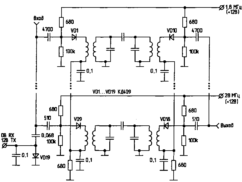
1. Electronic switch-band bandpass filters (Fig.1).
The main disadvantages of diode switching circuits preselectors are reducing their selectivity because of interference on the power circuit of diodes, narrowing the dynamic range and increased noise due to signal attenuation due to the finite resistance values of the diodes in the forward direction.
Foreign manufacturers of transceivers are used as special diodes pin diodes which reduce the above disadvantages to a minimum, and it is fully justified in the manufacture of transceivers low and middle class.
If you apply voltage +12 V output 1.8 MHz, then through the diodes VD1 and VD10 will flow a current of about 10 mA (as determined by the 680 Ohm resistance in the divider). The signal from the antenna through the diode VD1 is supplied to the coil, passes through a band pass filter 1.8 MHz and fed to the mixer. The remaining diodes electronic switch VD2...VD9 and VD11...VD18 closed reverse voltage (about +6 In), appearing on the resistors of the voltage dividers. This scheme allows to do only positive voltage.
Such a switch provides isolation between separate bandpass filters more than 50 dB. Loss of signal when using coils with diameter 5...8 mm is 8...10 dB. Losses can be reduced by increasing the direct current through the diodes, use a coil with a larger diameter or enter the high-frequency amplifier for loss compensation.
Antenna switch made the diode VD19. When receiving the voltage across the diode is 0 V.
It is closed, and the signal from input passes through one of the bandpass filters. When the transfer voltage of +12 V diode VD19 opens and thereby bypasses the entrance. In this case, the signal in the receive path does not pass.
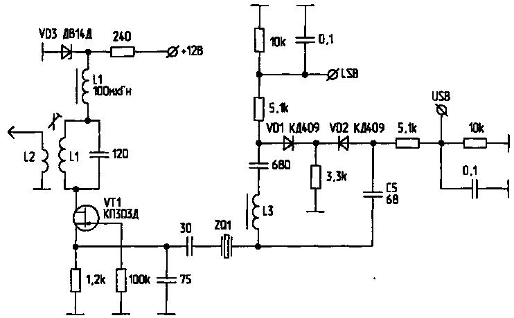
2. Switch crystal oscillator (Fig.2).

Fig.2
Using the specified electronic switch allows you to change the frequency of the reference crystal oscillator. When applying +12V to the input of the LSB, the diode VD1 (VD2 diode is closed), and in series with the quartz turns on the inductor, whereby the reference oscillator frequency decreases. When applying +12V to the USB input, the diode VD2 (diode VD1 is closed), and in series with the quartz turns on the capacitor C5. The reference oscillator frequency increases.
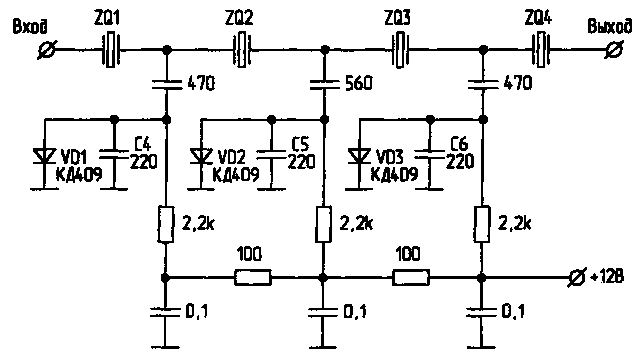
3. Switch lanes quartz filter

Fig.3
To switch bandwidth crystal filter of the transceiver is in the operating mode is SSB or CW, you can switch capacity included in the quartz filter using diodes. So, if you apply +12 To the crystal filter, open diodes VD1, VD2, VD3 and bypass the series capacitor C4, C5, C6, resulting in band quartz filter is narrowed from 2.5 kHz to 0.8 kHz.
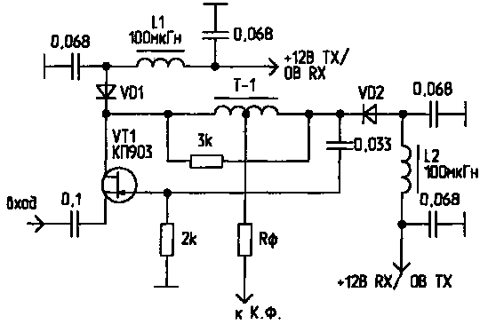
4. Reverse cascade (Fig.4).

Fig.4
This scheme is reversible cascade diplexer (which is an active load for the mixer in a wide band of frequencies) on the transistor QP many familiar. When taking it works as an amplifier with a common gate. In this case, the diode VD1 is open and the diode VD2 is closed. When the transfer transistor operates as a source follower.
Literature
1. Bashkatov V. Refinement of single Board universal tract. - The ham radio SW and УSW, 1997, No. 6.
2. Bunin S. G., Yailenko L. P. Handbook of shortwave radio. - K.: Machinery, 1978.
3. Gorshkov B. I. Elements of electronic devices. Guide. - M.: Radio and communication, 1988.
4. QST, N5, 1991.
Author: V. Bashkatov (US0IZ), Donetsk region, Gorlovka; Publication: N. Bolshakov, rf.atnn.ru


