


")

What's the mystery? Or e red in vain called these broadband transformers and guaranteed their work within six to ten octaves? This means, for example, that the transformer must maintain their properties, starting, say, from 1 MHz to hundreds of MHz.
In recent years, many of us acquired modern imported transceivers. And someone even "revealed" their transmission paths, and had the opportunity to work on the transmission in the continuous frequency range from 1.5 MHz to 30 MHz. The procedure of "disclosure", in General, is not practical for operation in the ether, but it gives them the opportunity to have at hand a powerful and convenient measurement system. The transmitter turns in a highly stable GSS, is provided with an SWR meter. By the way, a few people wondered why the import of the transceivers is guaranteed a constant output impedance equal to 50 Ohms and power throughout the frequency range.
Try to guess the "two times", how is this possible and how is achieved. Now, if skip signal through improvised broadband transformer is loaded to a resistor, the resistance of which is proportional to the square of the transformation ratio, depending on the transformer design and SWR meter transceiver will show the appalling figures 2 to 5 and more. In addition, these figures will vary depending on frequency And by increasing the signal power will be heating up the core. In short, we get just what they say on the air. And, as we had not rewound the transformer, a significant performance improvement we get.
So that, after all our "classic red" was wrong? Not at all! We simply did not read what he writes on there. And he writes about the need to compensate for the parasitic inductive components of the impedance of the transformer windings. In principle, gives good results as a series connection of tuning capacitors with the windings of the transformer, and parallel.
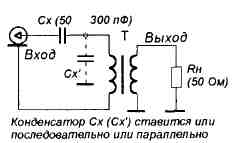
The effect is reminiscent of the resonance, the SWR at the input circuit "transformer-load" has a clear minimum at a certain value of compensating capacitor. But in contrast to the resonant circuit this circuit will be frequency-independent. In the transformer are greatly reduced losses. For example, a ferrite ring with a diameter of one centimeter can easily withstand the power of a hundred watts.
Applying such a pre-configured transformer can not worry for this node and to improve the overall CWS, for example, feeder system, selecting the load resistance only, removing only reactive components.
Author: Sergey Makarkin, RX3AKT; Publication: N. Bolshakov, rf.atnn.ru