Symmetric and asymmetric multivibrators for various purposes you can build not only bipolar, but also on field. One example that you will find in [1]. Given that field-effect transistors have several advantages over bipolar, the main of which - an extremely small current in the control circuit when operating at a low frequency or static mode, you can put that straight dvukhchastotnyi multivibrator, but only on field-effect transistors, will be in an advantageous position over the similar nodes collected on their bipolar counterparts.
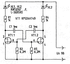
Scheme of the first multivibrator you see in pic. 1. His work is in many respects similar to the operation of the multivibrator on p-n-p bipolar transistors LEDs are flirting. The difference is that for closing each of the transistors VT1.1, VT1.2 it is necessary to apply a positive voltage gate-source higher than the cutoff voltage of these transistors (about 4 In). This happens whenever you switch shoulders of the multivibrator due to the presence of timing capacitors C1, C2. And that's why no need for a bipolar power supply.

Fig. 1
The switching frequency of transistors in the generator - once in 6 C. When installing high-quality electrolytic capacitors (low leakage current), capacity 100...4700 UF, it is possible to achieve switching transistors with a period of tens of minutes, which is unattainable for simple devices bipolar transistors.
The resistors R2 and R3 can vary several thousand times, for example, R2 can take 30 MW, a R3 10 kω. The multivibrator will become unbalanced. In the same way change the capacitance of the capacitors. Needed picking up these items, you can get at pin drain of one of transistors of very short pulses, following with a large duty cycle (100... 10000). If the device made according to the scheme of Fig. 1, instead of regular LEDs as the load transistors to turn on flashing, for example, L-36BSRD, any of them, blinking a few times, will entertain while flashing his neighbor. If necessary, the operation of the multivibrator at audio frequencies, the resistance of resistors R2 and R3 should be reduced in 10...20 times, and capacitors capacity to take several hundreds of picofarads.
Instead of conventional resistors R2, R3 can be set photoresistors (FGC, SF's, PPS's, FR, etc.). In this case, the switching frequency of the transistors will change several thousand times, depending on light level. It should only be noted that the resistance of resistors R2, R3 of less than 3 ohms generation can be broken.
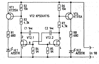
The multivibrator is made according to the scheme shown in Fig. 1, requires the use of field-effect transistors with a large initial current flow (10...30 mA). In the absence of such assemblies from KR, you can collect a similar multivibrator in the circuit shown in Fig. 2. Here FETs operate with a lower current flow, and to obtain sufficient brightness of the LEDs, set the current amplifier bipolar transistors VT1, VT4. The switching frequency of this multivibrator is about 1 Hz. If in place of transistors VT1, VT4 install powerful composite transistors from CT, as their load can be applied to the incandescent lamp. When R2 and R6 are not installed, since the transistors type CT contain their own built-in resistors.
If this multivibrator "refuse" to work, you should precisely select the resistors R3, R7. In the node, assembled according to the scheme shown in Fig. 1, you can use the micro matched pairs of field-effect transistors series CR, (C, 504) with the initial drain current greater than 10 mA. Most suitable KTV, KTV, but you can try and index A, B. When the polarity of the voltage supply and connection of LEDs, instead of the transistor Assembly, you can use two separate field n-channel transistor of the series K, K. If they will be a big cutoff voltage, the supply voltage can be increased to 15 V.

Fig. 2
For node, whose scheme is shown in Fig. 2, suitable chips CRT, CRT with any letter index, and in the selection of resistors R3, R7 - CRT, CRT. In addition, no configuration will work and many FETs series KP103, CP. Capacitors it is better to use non-polar, for example, small-sized K73-17 63 V. "Conventional" LEDs can be any of series AL307, CIPD, CIPD, CIPD and 1-1513, L-934, etc. Flashing - L-816BRSC-B, L-769BGR, L-56DGD, TWC and others.
Since FETs assemblies CRT(1 ...4) allow the maximum voltage of the source-drain not more than 10 V, the voltage of the multivibrators must not exceed 12 V. 10...
Literature
Publication: www.cxem.net


