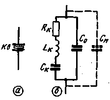
Quartz resonator (Fig.1,a) can be represented by an equivalent circuit in the form of a sequential circuit RкLкСк, shunted by the capacitance of plated surfaces and cartegories With, as well as capacity installation Cm (Fig.1,b).

Fig.1
The dynamic resistance R inductance LK and the capacity of the IC are determined by the mechanical resonance frequency of the quartz plate and the magnitude of the losses in the resonator. The value of the capacitor is determined With geometric dimensions and physical properties of the plate and the design of cartegories, for each resonator, it is constant. The capacity of the Cm depends on the design of the panels, the location of the wires, the capacitance between the points of connection of the resonator to the device, etc.
The resonator according to the equivalent circuit can be considered or as a sequential circuit RкLкСк, or as a parallel circuit RкLкCк(Co+Cm'). In accordance with this determines the behavior of the resonator at different frequencies.
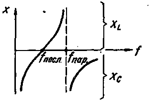
In Fig.2 shows the dependence of the reactance of the resonator from the frequency of the applied AC voltage. At low frequencies is crucial for the capacity of the IC, the resonator behaves as a capacitance.

Fig.2
With increasing frequency, capacitive reactance decreases and at a certain frequency fпосл called the frequency of the series resonance or the resonance frequency of the resonator, it becomes zero. The resonator exhibits the properties of a sequential circuit, its impedance is minimum and is equal to a resistance RC. The frequency of the series resonance is equal to

With further increase in frequency increases the inductive reactance of the resonator, and the frequency fпар resonator acquires the properties of a parallel circuit at resonance is infinitely large and equal in magnitude to the inductive and capacitive resistance.
At an even greater increase in the frequency starts to affect the action of the shunt capacitances Co and Cm, and the resonator acts as a condenser of small capacity.
The frequency of parallel resonance is expressed by the formula

As can be seen from the formula, the frequency fпар depends on the capacity of Cm, therefore, may vary within certain limits.
The ratio of the frequencies of the parallel and series resonance is determined by the expression:

The difference between these frequencies is small, the maximum difference is close to 0.4% of the frequency of the series resonance.
Therefore, the measurement of the resonant frequency of the quartz resonator devices can be produced with the same methods that are used to determine the resonant frequency of the circuits.
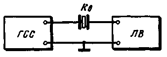
To determine the frequency of the series resonance of the resonator it is included between the output of the signal generator and the input of the vacuum tube voltmeter of high frequency (Fig.3). The output voltage of the generator should be of the order of 100 mV voltmeter is set to the limit of measurement 1-8 V. When the generator frequency equal to fпосл the voltmeter needle is sharply deflected to the right. Due to the high quality factor of the quartz resonator band for the transmission of frequencies is very narrow, so to change the oscillator frequency should be slow, otherwise the voltmeter because of its inertia does not have time to react to the received short voltage pulse.

Fig.3
The error of measurement of frequency with this method is determined by the error in the calibration of the generator. The disadvantage of this method is the considerable time spent on the passage of the ranges of the generator.
It should be borne in mind that some resonators have side resonant frequency, but at these frequencies, the voltmeter is significantly lower readings obtained at the main resonance frequency.
Literature
Radio No. 9, 1966, c.62
Publication: N. Bolshakov, rf.atnn.ru


