Fig.1
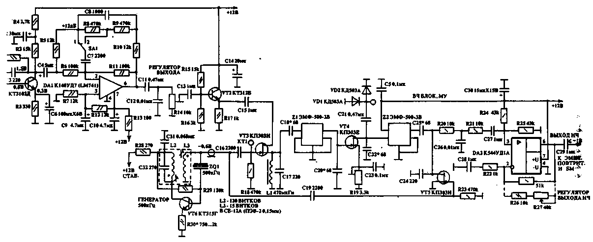
Block diagram of the device shown in Fig.1 and the schematic is in Fig. 2. As a microphone amplifier is used preamplifier-equalizer VT1, DA1. Stripe bass signal is in the range of 300 - 3000 Hz.

Fig.2 (click to enlarge)
The proposed scheme preamplifier-equalizer eliminates the decline of the high-frequency part of the spectrum of speech and significantly improve intelligibility. In the proposed scheme, the rise of the amplitude VA 12 dB occurs at a frequency of 2700 Hz. The equalizer resistors R5, R10, R6, R11, R8, R9 and capacitors C7, C8 should have the range of variation of ± 5 %. Through the emitter follower to VT2 signal is supplied to the circuit proper RF limiter (VT3 - VT5, Z1, Z2.DA2), developed UV9DZ. On VT3 CPI made the first mixer. The signal from the crystal oscillator 500 kHz with an amplitude of 0.6 - 0.7 V is supplied to the gate VT3. On the stock VT3 enters a low-frequency signal with an amplitude of 150 - 160 mV. The output Z1 is allocated SSB signal, limited by diodes VD 1, VD 2 and filtered through Z2. Further, the signal demodulated using VT5 and enhanced DA1.
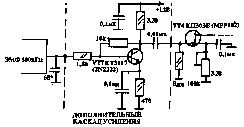
If necessary to adjust the output level instead of the R9-51 should be applied to the chain shown in the diagram by dotted lines. The microphone amplifier of the transmitter is not used, because it is not needed. In the quartz oscillator 500 kHz using the R30 set the level of the output voltage of 0,6 - 0,65 V. the Degree of constraint may be defined as the ratio of the RF voltage at the drain VT4 disabled when the diodes VD1, VD2 to the voltage at the same point after connecting diodes (-0,6). This value is 7 to 8 dB. To increase the level limit to 15 dB between Z1 and VT4 is possible to include an additional stage of amplification to VT7 (Fig. 3).

Fig.3
Gain control VT4 is performed using a variable resistor R19 or the adjustment of the output of the preamplifier - equalizer R14. The value of the resistor R19 is convenient to choose such that the minimum gain of the stage on VT4 to prevent the reduction of the optimal level SSB signal with minimum restrictions. This is important when comparing the signal of the radio transmission at the minimum and maximum levels of restriction.
After a long operation of the devices were installed bypass relay (input and output). This commutation becomes very convenient for local QSO, because the signal level at point of reception is great and the restriction may reduce the intelligibility of the signal.
When conducting a DX QSO, or in conditions of QRM, QRN limited signal has a high quality and intelligibility.
Author: I. Podgorny, Minsk; Publication: N. Bolshakov, rf.atnn.ru


