This circuit was developed to allow watch crystals to be used in an existing CMOS oscillator circuit that was to run from a 12V supply. The problem is that these crystals only work up to a supply voltage of about 6V. Any more than that and the crystal will be over-driven, causing it to shatter. This circuit solves the problem by using LEDs 1 & 2 and a 470nF capacitor (C3) to limit the drive to the crystal to about 4V peak-to-peak. Note that it may be necessary to adjust C1 & C2 to ensure reliable start-up and stable oscillation with some crystals. However, the C1:C2 ratio should be maintained. As a bonus, the two LEDs both glow, giving a visual indication that the oscillator is working.
Circuit diagram:
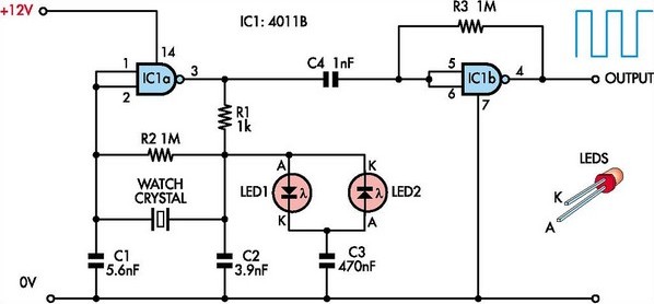
Safe Oscillator Circuit Diagram For Watch Crystals
Editor's note:
The relatively high values used here for capacitors C1 & C2 will load the crystal, which means that the oscillator will run at less than the nominal crystal frequency (32.768kHz).
Author: Duncan Graham - Copyright: Silicon Chip Electronics


")
