


")

Circuit diagram:
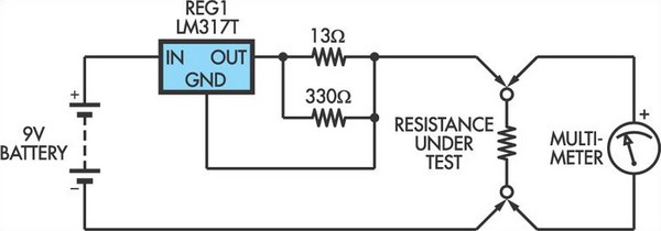 Low Ohms Adaptor Circuit Diagram For DMMs Based On An LM317 Regulator
No on/off switch is required since no current will be drawn when no external resistance is connected across the Test terminals. Accuracy using 1% resistors should be within 5% and this could be improved by measuring the current, adjusting the resistance between the output and Adj pins of the LM317 to provide a precise 100mA. Before using the adaptor, check that your meter is not likely to be damaged by having the full output (6V+) applied when it is set to a low voltage range. Similarly, be aware that the voltage and current output of the adaptor may damage components if you use it for "in-circuit" tests.
Author: Peter Chamberlain - Copyright: Silicon Chip