The most simple are the ICS ROMs that can not be reprogrammed, i.e., specifying writing in them once the information cannot, as a rule, any way to change it. These chips are supplied "clean" - they recorded only zeros. When programming the user in the right words and discharges; it burns the jumpers in the internal shiratori matrix ROM. records unit.
Most often as "memory" is used chip CRT representing the storage device 32 eight-bit words. Its functional scheme is shown in Fig. 1. It consists of the output of address decoder D1, matrix h bit D2 and the output buffer stage D3 is open collector, allowing to read data from the ROM in the presence of an enable signal at the input of the inverter D4.
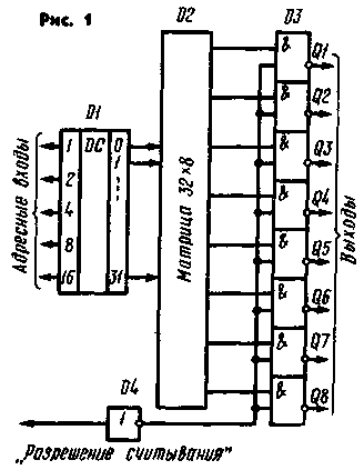
Fig.1. Chip CRT.
Dignity ROM CRT is that when turning the power off logged information is kept indefinitely, and that combining the corresponding address inputs of multiple chips, it is possible to increase the bit width of the memory.
In Fig. 2 is a diagram of a simple driver code "Fox", made on the basis of the ROM CRT, which allows you to create eight different code packages.
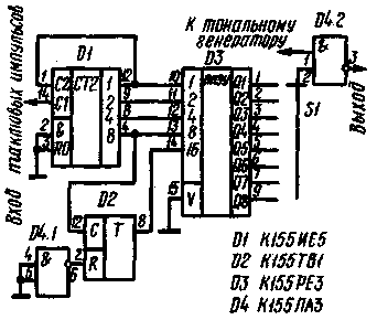
Fig.2. Scheme simple driver code "Fox"
The code length of the parcel is limited in this case 32 clock intervals, with a duration of one "point" is that sufficient to generate a code first three "foxes" to extract all the necessary time intervals between the "dash", "dot" and signs. Code corresponding to "the Fox" is selected by switch S1. In Fig. 3 is a timing diagram of the output signal of the ROM in the formation of signals of "MINE" and "MOS".
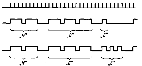
Fig.3. Chart of the output signal of the ROM
For programming the ROM pre-create a table in which for each word indicate the status of each category of "memory". As an example in the text, the table of programming. to form code "Fox". It can be seen clearly, as the outputs of the ROM are formed corresponding code of the parcel. By changing the frequency of clock pulses, the transmission speed can be adjusted.
Table 1
Address number
The state of the input
The program output
1
2
4
8
16
QI
Q2
Q3
...
Q8
0
0
0
0
0
0
1
1
1
0
1
1
0
0
0
0
1
1
1
0
2
0
1
0
0
0
1
1
1
0
3
1
1
0
0
0
0
0
0
0
4
0
0
1
0
0
1
1
1
0
5
1
0
1
0
0
1
1
1
0
6
0
1
1
0
0
1
1
1
0
7
1
1
1
0
0
0
0
0
0
8
0
0
0
1
0
0
0
0
0
9
1
0
0
1
0
0
0
0
0
10
0
1
0
1
0
1
1
1
0
11
1
1
0
1
0
1
1
1
0
12
0
0
1
1
0
1
1
1
0
13
1
0
1
1
0
0
0
0
0
14
0
1
1
1
0
1
1
1
0
15
1
1
1
1
0
1
1
1
0
16
0
0
0
0
1
1
1
1
0
17
1
0
0
0
1
0
0
0
0
18
0
1
0
0
1
1
1
1
0
19
1
1
0
0
1
1
1
1
0
20
0
0
1
0
1
1
1
1
0
21
1
0
1
0
1
0
0
0
0
22
0
1
1
0
1
0
0
0
0
23
1
1
1
0
1
0
0
0
0
24
0
0
0
1
1
1
1
1
0
25
1
0
0
1
1
0
0
0
0
26
0
1
0
1
1
0
1
1
0
27
1
1
0
1
1
0
0
0
0
28
0
0
1
1
1
0
0
1
0
29
1
0
1
1
1
0
0
0
0
30
0
1
1
1
1
0
0
0
0
31
1
1
1
1
1
0
0
0
0
Note. Program output Q1 - code "MY", Q2, "MY", Q3 is "MOS".
In some cases there is no need to form a few words, and Vice versa, you need to get one "long" multi-bit word, for example, the codes "MOSS", "M05", from the General call or radio call sign, used For this multiplexing outputs of the ROM (see Fig. 4).
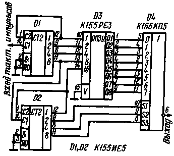
Fig.4. Multiplexing outputs of the ROM.
With such a construction site first 32 characters are displayed from the first digit of the ROM, then the device automatically switches to output information from the second digit and so on until the eighth, "Depth" output word in this case is increased to 256 bits.
The same site can be used in "the Telegraph key" with "memory" described in "Radio" No. 8 for 1980, It is significantly structurally simplify the key.
On the basis of the described examples it is possible to develop a range of digital devices and software for different purposes, characterized by simplicity and small size.
The ROM is programmed in special units semi-automatic and automatic types, in which a pre-adjusted program recording is transferred to the memory. In Amateur conditions, when there is no need of programming a large number of chips, the most suitable installation manual type, the diagram of which is shown in Fig. 5.
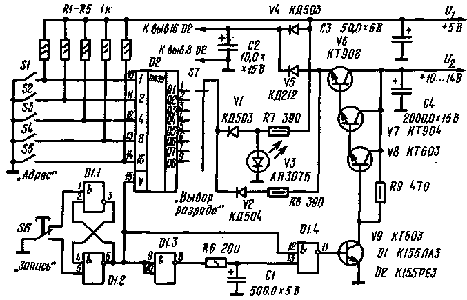
Fig.5. The programming ROM
Programming is carried out sequentially for each word and the category. The word address set switches SI to S5, and the choice of the discharge - S7. The components of D1.1 and D1.2 is assembled, the single generator of rectangular pulses with a duration of 50...100 MS. According to the programming instructions single programmiruyutsya pulse amplitude of 10...12.5 V should be supplied to the programmable output level and the output power is shunted by the capacitor 10...15 UF. The rise time of the pulse should not exceed 1 µs. To ensure this requirement, in the device, enter the amplifier transistors V6-V9 with filter capacitor C4. The output of programmable discharge pulse is supplied through the resistor R8 and the diode V2 and the output power through the diode V5. The elements V1, V3, R7 is executed, the control unit programming. If the led V3 is not lit, it indicates the absence of record information in the appropriate cell of the ROM.
When you press the button S6 at the output of the element D1.2 level 1 appears allowing entry into the ROM. Formed the programming pulse is fed to the ROM with the emitter of the transistor V6. Entry control after releasing the button S6. If writing failed, increase the voltage U2 steps of about 0.5 to no more than 14 In, each time generating an attempt programming. It should be noted that according to the specifications of IP CRT coefficient programmability is at least 30% of the total number of IP that is guaranteed to be programmed only every third chip.
After programming the ROM CRT it is necessary during the day to stand at a temperature of 100° C.
In Amateur conditions, the suitability factor can be substantially increased, since in some cases there is an excess of free words and bits that can go with reprogrammability pre-selected.
Author: A. Puzakov (UB5MOU), Kommunarsk; Publication: N. Bolshakov, rf.atnn.ru


