All filters are made on the crystals frequency 10.645 MHz.
I have tested the following 6 types of filters:
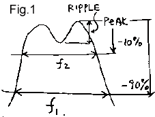 Fig1. shows the definitions on this page.
f1 = bandwidth.
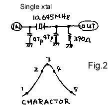 Single-chip filter (fig.2) Point Frequency Voltage Attenuation No. MHz V dB 1 10.62337 0.06 -20 2 10.64392 0.54 -0.9 3 10.64510 0.6 0 4 10.64641 0.54 -0.9 5 10.65474 0.06 -20 charactor
* impedance 500 Ohm (at least in the center of the passband)
* bandwidth f2=2.49 kHz
* factor sharpness 8%
* flatness (ripple) - no
* this filter is good for AM receivers
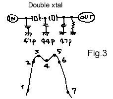 Two-crystal filter (fig.3) Point Frequency Voltage Attenuation No. MHz V dB 1 10.63578 0.055 -20 2 10.64400 0.5 -0.9 3 10.64488 0.55 0 4 10.64592 0.53 -0.3 5 10.64628 0.54 -0.1 6 10.64696 0.5 -0.9 7 10.65083 0.055 -20 charactor
* the impedance of 82 Ohms (min in the center of the passband)
* bandwidth f2=2.96 kHz
* factor sharpness 20%
* uneven bandwidth 0.3 dB
* this filter is good for simple SSB receiver.
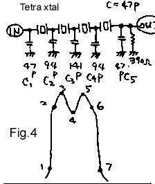 Triple filter (fig.4) Point Frequency Voltage Attenuation No. MHz V dB 1 10.64309 0.05 -20 2 10.64441 0.45 -0.9 3 10.64484 0.5 0 4 10.64564 0.43 -0.13 5 10.64650 0.5 0 6 10.64693 0.45 -0.9 7 10.64786 0.05 -20 charactor
* impedance 27 Ohms (min in the center of the passband)
* bandwidth f2=2.52 kHz
* factor sharpness 52%
* this filter is good for SSB receivers and transmitters.
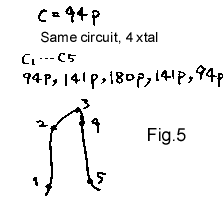 Chetyrehkolenny filter (fig.5)
with large capacitors Point Frequency Voltage Attenuation No. MHz V dB 1 10.64319 0.04 -20 2 10.64408 0.36 -0.9 3 10.64509 0.4 0 4 10.64555 0.36 -0.9 5 10.64618 0.058 -20 charactor
* impedance 21 Ohms (min in the center of the passband)
* bandwidth f2=1.47 kHz
* a factor in the severity of 49%
* this filter is good for narrow-band filters in SSB receivers.
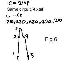 Chetyrehkolenny filter (fig.6)
with more capacitors Point Frequency Voltage Attenuation No. MHz V dB 1 10.64350 0.02 -20 2 10.64373 0.18 -0.9 3 10.64395 0.2 0 4 10.64405 0.18 -0.9 5 10.64473 0.02 -20 charactor
* impedance 40 Ohm (min in the center of the passband)
* bandwidth f2=0.32 kHz=320Hz
* factor sharpness 26%
* this filter is good for narrowband filters CW receivers.
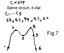
Chetyrehkolenny filter (fig.7)
small capacitors Point Frequency Voltage Attenuation No. MHz V dB 1 10.64219 0.05 -20 2 10.64493 0.40 -1.9 3 10.64668 0.35 -3.1 4 10.64848 0.55 0 5 10.64906 0.50 -0.9 6 10.65014 0.05 -20 charactor
* impedance 82ohm (min in the center of the passband)
* bandwidth f2=4.13 kHz
* factor sharpness - 52%
* this filter is good for AM and narrowband FM receivers.
My findings:
Author: Kazuhiro Sunamura, JF1OZL, Japan, translation of Nikolai Bolshakov, RA3TOX; Publication: N. Bolshakov, rf.atnn.ru


