The power supply unit (PSU) is assembled from available elements. It requires almost no establishing, working in a wide range input AC voltage, provided with protection against overcurrent. From previously known designs this the power supply is characterized by simplicity and reliability, as well as the possibility of using an external control signal to remotely turn on and off the stabilizer. This simple scheme allows to obtain good stabilization factor and the high output current, which depends on the number of control transistors, connected in parallel.
Technical capabilities
Adjusting the output voltage in the range 3...20 Fixed voltage V. 13.8 V with overvoltage protection.
Instability of output voltage in the range of regulation change the voltage of the mains supply by 10% from the nominal value for any permissible the load current does not exceed 0.03%.
The instability of the output voltage when the load current from the maximum valid value to zero does not exceed 0.1%.
The amplitude of the output ripple voltage does not exceed 1 mV RMS value in the control range for any permissible current load.
Temperature coefficient of output voltage over the entire range of regulation for any permissible load current when the temperature of the environment from 5 to 40°C does not exceed 0,02%/deg.
Protect the power supply against overload and short circuits. May be grounded output circuits of positive or negative polarity, as well as parallel and the sequential operation of two identical power supplies. You can connect and shutdown of loads without relief.

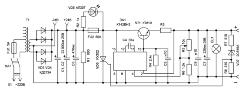
Fig.1. A circuit diagram of a power supply
A circuit diagram of the power supply unit shown in Fig.1. The power supply assembled by the classical scheme of successive compensatory stabilizer voltage. The device consists of two functional parts: voltage regulator and node protection. The stabilized power supply consists of step-down transformer T1, a powerful rectifier diodes VD1-VD4, the filter capacitors C1-C3 and stabilizer DC voltage on the chip DA1. Continuous adjustment of output voltage is effected by potentiometer R5.
Chip CAN allows to significantly simplify the design of power supply, to improve its quality characteristics, improve reliability, reduce the dimensions. This chip is an adjustable voltage regulator with the system of protection against overcurrent and short circuits in the load circuit, provides the output voltage from 3 to 30 V at currents up to 1 a, And also allows external control signal to remotely turn on and off the stabilizer. In by triggering the thermal protection system reclosing stabilizer possible only after cooling of the chip. The electrical circuit of the chip considerably complicated as compared with the scheme stabilizers CAN, for KEN by introducing a two-stage differential UPT with dakotabilities the bipoles, which significantly increased voltage stability, and the presence of powerful pass transistor is provided a load current up to 1 A.
The appointment of pins: 2 input system protection; 4 - input feedback; 6 - shutdown circuit; 8 - General conclusion, electrically connected to flange; 11, 17 - correction; 13 - exit; 15 - entrance.
To increase the power output of an integrated circuit transistor is used the structure of the n-p-n, the collector of which is connected to the output of the power source, and the emitter is connected to the output of the rectifier. The base of the transistor connected to the output the output of the stabilizer. When triggered, the system of protection against overcurrent the output voltage is reduced to almost zero.
The principle of operation
Circuit control voltage operates as follows. When the current flows through the resistor R3, the voltage drop affects the system input protection chips and closes the control transistor VT1. To put the PSU in working condition after eliminating the cause of overload, it is necessary to short time to turn off the PSU from the mains switch SA1 Output voltage and current monitored devices.
Included in the circuit of the rectifier thyristor reliably burns the fuse, if the output voltage for any reason becomes higher than acceptable. Voltage protection against overvoltage depends on the Zener diode. At the moment protection operation led should be illuminated, indicating that the fuse is lit. This node if desired, can be eliminated.
Design
The entire device is housed in a metal enclosure dimensions HH In mm. the upper and lower covers (from the rear wall of the radiator) drilled holes with a diameter of 4 mm for improved cooling. To strengthen the lower cover small legs, which you can use the caps from the tubes.
On the front of the front panel are: toggle enable network SA1; nests for fuses FU1, FU2 (fuse located on the front panel of the unit power for ease of replacement); voltmeter RA1 and ammeter RA (not shown); a potentiometer R5; HL1 led; indicator light EL1; weekend terminals 3...20 In connector and 24 V. the Latter is used for power supply electronic devices unregulated voltage. On the rear panel is a rubber grommet through which derive the mains cable to the desired length with plug X1 at the end.
The PSU is mounted on the circuit Board of one-sided glass the fiberglass. Perhaps the use of resistors MLT, C2-33, S1-4. Oxide capacitors C1, C2 type K50-46 or imported. If necessary, the number or capacity can be increased. The capacitors C3, C7, it is desirable to apply tantalum, for example, CB or similar. Locking and corrective capacitors C4-C6 type. Km, soldered directly to the pins of the chip.
Regulating transistors and integrated stabilizer installed on the radiator, located on the posterior wall of the housing. They should be securely isolated from radiator mica spacers with a thickness of 0.05 mm, pre-lubricated heat-conducting paste. KPT-8, or placed on an insulating stand the heat sink.
Diodes VD1-VD4 mounted on a heat radiator and isolated from the body. In this BP applied to the diodes type CD, two in parallel. Diodes can CD replace KDA (more inclusion in parallel) or any other, so that allowable forward current was at least 20 A. Instead of the thyristor VD5 type CU perhaps the use of thyristors T4-10, T10-16.
Potentiometer R5 type SP-1, or any other, suitable for installing on front panel of the power supply. Takavarasha resistors C5-16 is installed near transistors mounted Assembly isolated from the hull mounting.
The instrumentation of RA1 and R with any current full deflection from 0.05 to 1 mA and easy to read scale. The scale is graduated in 1 V and 1 A. you Can use microammeter type M with a measuring range of 100 μa. In this case the additional resistance and shunt resistors should be selected.
Power transformer T1 must be greater than the power consumed by the load. The estimated capacity of 450...500 watts. The primary winding has the taps to select the optimum voltage on the secondary winding. The inclusion of more the number of turns of the primary winding to reduce power dissipation transistor VT1 while maintaining the basic properties of the power supply Secondary winding of the transformer produces a voltage h V. To reduce the size PSU you can use a transformer with a toroidal magnetic core.
The switch SA1 type TB1, it is better to use appeared on the market of imported network switches with built-in lamp, which indicates the mode of inclusion. Resistor R3 type C5-16 or cut nichrome wire with a diameter of 1 mm and a selected length. The resistance of this limiting resistor adjustment current protection is calculated by the formula:

Before enabling BP to the network check the correctness of the installation. Include BP in the network and measure the voltage on the capacitors C1-C3. It should be about 24 V. For exemplary devices should be graded scale PA1 and RA and choose the additional and shunt resistors.
If necessary, you can increase the output current of the source parallel the required number of regulating transistors. In the circuit of the emitter transistors should be included takavarasha resistors resistance of 0.1 Ohm, and also use a larger power transformer and increase the number diodes in the shoulder of the rectifier.
When two transistors CT in parallel BP long time "holds" the current 22 And at a voltage of 13.8 V. When properly executed installation “drawdown” of the output voltage does not exceed 0.2.

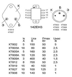
Fig.2. The parameters and the Pinout of the transistor
Transistor VT1 CT it is permissible to replace any of the series CT, CTA, CTA, CTA, CTA, CT, CT, CT or other powerful with the allowable current collector is not less than 5 and allowable voltage collector-emitter more voltage. The parameters and the Pinout of the transistor shown in Fig.2. Diodes VD1-VD4 any rectifier with a valid direct current of 5 A and the corresponding voltage. The led can be applied any type. The circuit is made stranded mounting wire 4...6 mm2.
This PSU can also be used as a charger, if you provide it with the timer, which would shut off the unit after a specified time required for charging of the battery.


