


")

Every ham knows that without a source of constant and alternating voltages different values in practical work is not enough. He desired to establish radiocontrol, repairing equipment, charge batteries, test the motors and relays, to conduct physical experiments. All this is possible to do with using a universal power supply, which we offer the readers.
The device allows to obtain a smoothly varying voltage in the range of 2-300 In up to 900 mA of AC and 600 mA DC or 2-22 In at currents up to 6 A.
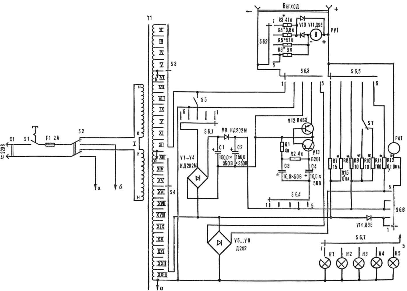
Fig. 1. Schematic diagram of power supply
With the switch S6 (Fig. 1) five provisions set mode a power supply unit, which is confirmed by the corresponding lamp H1-H5.
Voltage in the range of 2-22 In choosing step 2 In the switch S4, and the range 2-300 In S3 through 26 V.
The switch S2 of the transformer T1 is transferred to the autotransformer mode to power more powerful current consumers.
Alternating current is converted to DC bridge rectifiers diodes V1-V4 and V5-V8. To eliminate the possibility of failure of the filter C1, V9, C2, set the toggle switch S5, which should be in the "off" position when high-voltage load is disconnected.
The rectifier V1-V4 works in universal mode. In fourth position switch S6.1 is energized 2-22 V. In the third position S6.1, with the closed switch S5 to the bridge connects the high-voltage winding of the transformer.
Rectified voltage mode 2-300 In with filter C1, V9, C2 is supplied to the output terminals of the power supply. Mode 2-22 DC voltage comes on the second filter, transistors V12, V13.
Rectifier diode V5-V8 connected to T1 constantly.
The magnitude of voltages and currents is controlled by two dial indicators PV1 and PA1. The scale of the ammeter has two full scale value: 0-900 mA and 0-6 For A. measuring currents of up to 90 mA toggle switch S7 include additional shunt, dividing the reading by 10.
Design and details. Perhaps the most time-consuming process - manufacturing of the transformer. Based on the TS-180-2 - power transformer from the TV black-and-white image. It has a magnetic tape SLH of steel The e-310 is 0.35.
The transformer is disassembled, wound with his secondary frames and more network winding 58 of turns (pins 2-3). And the network winding turns 375 the PEV-1 0,69 (pins 1-2) leave unchanged. Then on one of frames are placed in the order given in section XXIII-XVII, XII, XI, X, IV, III, II (563 loop), the second - XVI - XIII, IX-V (508 turns).
Section II to XI contain 96 turns, and XII has a loop 34 of PEV-1 0,69. Winding HHS-XIII wound wire sew-1 of 1.5 to 7 turns in each section. It is possible to wind two wires of smaller cross-section, for example, sew-1 0,74.
Each series winding isolate 2-3 layers of oiled transformer paper. The findings are soldered to the petals, located on the frames, and tag.
Between the joints of the U-shaped halves of the magnetic tape if necessary lay 2-3 layers of capacitor paper, that the backlash was 15-30 microns. Then the "humming" of the transformer will be much weaker. After Assembly, connect between a network of winding, as shown in the diagram.
Transistors and diodes D installed on a heat sink (see Fig. 2) - aluminum plate size HH mm at first and put together two aluminum the plate thickness of 2 mm in the latter.
Fig. 2. Power transformer with batteries installed:
1 - heat sink for the diodes D, 2 - heat sink for transistors, 3 - panel with
diodes CDM, 4 - panel with resistors R3-R6, 5 - laminated bakelite Board.
Instead of the transistor PBA be possible to apply GTA, P209, P, and instead P suitable P, P, P, P with any letter index. Diodes can KDM replace CDC, KD202L or DB, CD, United by two in parallel; D - CD with any letter index or D243, D, D; DE - any series D2 or D9.
Capacitors C1, C2 C50-12 have a common casing. They can be replaced by any other with a working voltage of at least 350 V. Instead of the capacitors C50-6 (C3, C4) can apply C50-3. Fixed resistors MLT-1 or VS-1.
S1 - push-button switch from electrical appliances, S2 - switch TP-1-2, S3, S4, S6 - disk switches, S5, S7 - toggle TB2-1.
PV1 - voltmeter C4200 with current full deflection 250 µa RA1 - microammeter M with current full deflection of 50 μa. These measurement the devices can be replaced by any other within the specified sensitivity. The scale of Indicators is produced in accordance with the General .
Shunts R7, R9, R10 wound nichrome wire Ø 0.3 mm on the hulls of resistors Sun-0.5, remote pre-conductive layer. The same wire, but Ø 0.15 mm is wound and shunt resistor R11. Shunts R8 and R12 are segments nichrome wire Ø 0.7 mm and a length of 2-3 cm of Nichrome wire can replace manganin or Konstantinovy, but the length of the winding is then needed zoom in twice, because the resistivity of these materials is less. Shunts are installed on the switch S6.
N1-N5 - up lamp 2 km calculated for a voltage of 24 V. They can replace with any other, removing the corresponding voltage from the transformer.
The PSU is housed in a duralumin case the size HH In mm. the side walls are made 7-8 longitudinal ventilation slits size h mm, and the base - 2-3 hole Ø 20 mm.
Special chassis unit does not have. Bearing elements are the front panel and the power transformer. Wiring is stranded wires, collected in the bundles.
The front panel is the size of x mm made of thick duralumin sheet 2 mm it was put a sheet of paper with the words, made with black ink, and covered top Plexiglas thickness of 2 mm.
A push-button switch S1 is mounted on top of body.
If the installation is performed correctly and all parts are serviceable, the power supply starts to work immediately after you turn it in. You will need to adjust only the magnitude of the additional resistors and shunts the arrow indicators.
Author: A. Medvedev