Below the power source is designed using three-terminal integral stabilizers, is quite versatile and can be successfully be used to power the microprocessor.
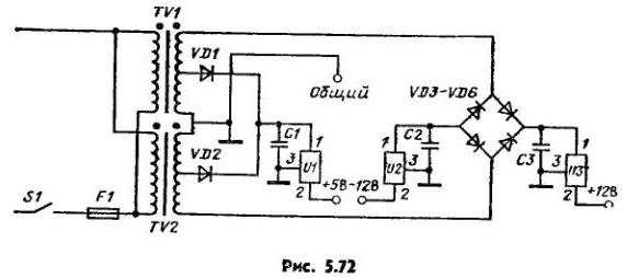
The source circuit shown in Fig. 5.72.

One integral stabilizer type 7805 (U1) provides a positive output voltage 5 V at rated current of 1.5 A.
Stabilizers 7812 (U3) and 7813 (U2) form a bipolar output voltage, values equal to ±12 V. Maximum output current of these channels also is 1.5 A.
The circuit components have the following options: electrolytic capacitor C1 10 000 μf, 35 V, electrolytic capacitors C2, C3 - 7000 µf 35 V; diodes VD1-VD6 - 50 3 A; fuse F1 - 1 A.
The source uses two identical transformer (TV1 and TV2), secondary windings which are the middle points of the bends, the total voltage on each of the secondary winding is equal to 12.6 V, rated current of 5 A.
The figure shows that the primary windings of the transformers connected in parallel, and secondary winding connected in series according to provide the required stabilizers U2 and U3 levels of input voltages.
Point Association of secondary transformer windings grounded. The lower Polubotko secondary winding of the transformer TV1 and upper Polubotko the secondary winding of the transformer TV2 together with diodes VD1 and VD2 and capacitive filter C1 form a full-wave rectifier with the output of the zero point.
The output of this rectifier are generated positive relative to the earth voltage (about 9), which is input to the integral stabilizer V1.
Full secondary windings of the transformers, diodes VD3-VD6 and capacitors C2, C3 are two full-wave rectifier with the output of the zero point, one of which provides a negative (capacitor C2), and the other positive (on the capacitor C3) voltage whose value is approximately equal to ±17 V. These stresses are used as input for the stabilizers U2 and U1. General conclusions all three stabilizers "grounded".
Thus, the power supply has three outputs: one with positive a voltage of +5 V and two with equal but opposite voltages of ±12 V.
Author: R. Treister


