


")

VTTC owe their existence to the invention and propagation of high-power generator electron tubes, capable of creating electromagnetic oscillations capacity in hundreds and thousands of watts. Unlike spark generators that create recurring tutu damped high frequency oscillations, tube capable of generating a continuous signal that can be modulated by to the amplitude.
This is a classic vacuum-tube oscillators, the load which the primary winding Tesla transformer. Such devices are popular among foreign and domestic fans, although to a lesser extent than SGTC. The main difficulties when they are created - big size powerful generator of lamps, the need for their air or even water-cooling and high-voltage anode supply.
Consider depicted in Fig. 9 is a diagram of the vacuum tube Tesla transformer on modern components. This is a classical oscillator with inductive (transformer) feedback. Lamp VL1 (pentad GC-71, widely used in Amateur radio transmitters) includes a triode - all mesh together. Pentode inclusion, which decreases internal capacitance of the lamp and reduces the probability of excitation, in this case has no advantages, because the excitation is required.
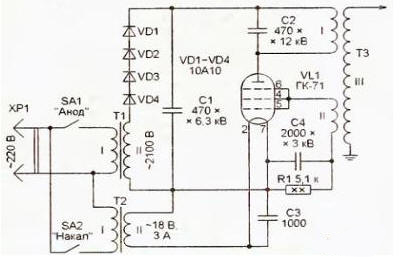
Fig. 9
The anode load of the lamp resonant circuit formed by the winding I of the transformer. T3 and the capacitor C2. Next to the winding on the same frame is the feedback winding II. Induced therein a voltage is supplied to grid lamp, providing required for the generation of positive feedback. The variable component of the grid current is shorted to the cathode through a capacitor C4, and the constant flowing through the resistor R1, it creates a voltage drop, applied disadvantage to the grids of the lamp.
This is the automatic voltage offset. Increasing in absolute value, it partially covers the lamp by increasing the amplitude of the RF signal, and if it decreases too reduced, leading to an increase in the amplitude. So follows the oscillation amplitude is kept constant. Selection resistor R1 can to some extent regulate the power output of the generator. Blocking capacitors C1 and C3 minimize the penetration of high frequency the voltage in the supply grid.
The source voltage supplied to the anode of the lamp VL1, consists of a transformer T1 from kitchen. Microwave ovens and half-wave rectifier connected to consistently diodes VD1-VD4. The maximum value of the pulsating frequency 50 Hz output voltage of the rectifier is about 3 kV. The signal fed to such the voltage generator has the form of flashes HF oscillations, following a frequency of pulsation. This somewhat simplifies the operation mode of the lamp a voltage of 3 kV is more acceptable for her in continuous mode) and a positive affects the number and shape of the observed discharges.
The filament voltage is supplied to the lamp VL1 from the transformer T2. It is important to note, what to include the device in two stages. First of all switch SA2 include the intensity. and only a few tens of seconds when the cathode of the lamp warms up, served anode voltage, closing the switch SA1. Connecting the transformer T1 to the network through an adjustable autotransformer (Latr) it is possible to smoothly increase the anode voltage when you turn on and adjust it the process of experimentation.
The design of the transformer T3 shown in Fig. 10. The windings I and II are wound on stretch plastic plumbing pipe with a diameter of 160 mm. Winding I consists of 30 turns of insulated wire 4 mm Winding II contains 20 turns enameled wire with a diameter of 0.22 mm. output winding (III) is the same. in the previous cases, is wound on the bottle from kefir.
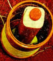
Fig. 10
If there is no light GC-71, you can use less powerful SU-50 and used in the line scan TV lamp PS, 6P45S. To increase the power of these lamps can be enabled in parallel. Don't forget to pick up the transformer T2 with a voltage in the secondary winding corresponding to nominal filament voltage applied to the lamp.
Tuned circuit in the anode circuit of the lamp VL1 must be configured to resonant frequency of the winding III of the transformer T3. This should be measured the inductance of the winding I and the well-known formula to calculate the capacity. Capacitor C2 should be a high voltage, for example, SWИ-3. Good results are obtained the use of a vacuum variable capacitor.
If you measure the inductance is not possible, from winding I can do a few taps and adjust the number of turns in her greatest length the resulting discharges. it makes sense to have the ability to move the winding II relative to the winding I for selection of optimal feedback ratio.
As in the previous case, remember that the device comprises elements under life-threatening stress. Any touching it when the power is unacceptable. The whole adjustment and refinement of the device can be made only after it is disconnected from the network and forced discharge all high-voltage capacitors.
Overall, it can be noted that compared to the SGTC VTTC works somewhat "softer", and its design is more convenient due to the absence of a spark gap which is gradually burns and requires adjustment. it is interesting to note that the discharges do not like those. what happened with SGTC. Very unexpected spiral shape streamers (Fig. 11), the reason the author is unknown.
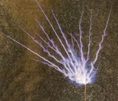
Fig. 11
To compare the shape discharges in pulsed and DC plate voltage, half-wave the rectifier anode voltage was replaced by a full-wave rectifier (diode bridge) and added a smoothing capacitor of a large capacitance. The result is shown in Fig. 12.
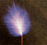
Fig. 12
The differences are clearly visible. When the high frequency voltage generated by the flashes, each streamer there is only a half period of mains voltage. The new discharge is not repeats the old way, and rushes to another place. We see several long single streamers. When continuous generation of the "torch" lit. It is very similar to the usual flame and even rejected if on him to blow. However, in still air, the flame is directed not strictly upward, as normal flame, and at some angle to the vertical. Probably it is associated with the structure of the magnetic field around the transformer.
The difference in the modes is well marked and the ear: the pulsed heard a loud roar from the 50 Hz, and in continuous - only a slight hiss. It is theoretically possible use a Tesla transformer as the source of the sound, if to the modulated audio signal generator. There won't be an AM transmitter, operating at the resonant frequency of the Tesla transformer.
There had been an interesting experiment with "ion engine" - a pinwheel of conductive material placed on the edge of the output electrode Tesla transformer. Streams of ionized particles, floating with sharp curved the ends of the blades of the vane in one direction, creating a jet thrust, causing her in the movement.
To obtain good results, the turntable should be light and well balanced. To make the photograph shown in Fig. 13, the anode the voltage across the lamp VL1 had to be reduced to 1000 V. otherwise, the rotation was too fast and pinwheel often falling.
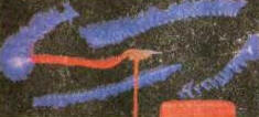
Fig. 13
It should be noted that despite 100 years of history, the Tesla transformer more has not been explored yet. For example, the author has failed to find an explanation for the spiral form streamers, accurate methods of calculating the input resistance of the Tesla transformer and his exact agreement with the generator, method of calculation of length discharges and influence their self-capacitance to the resonant frequency of the transformer. Judging by all these little problems were studied and practically not covered in available sources.
In General, the Tesla transformer is very extensive and not fully explored field for the experiments. Among the Amateurs even argued that the efficiency of the Tesla transformer exceeds 100%. as he draws "free energy" of space. This. of course. is not so. Any violations of the law of conservation of energy when experiments with Tesla transformers is not seen.
As mentioned above, the Tesla transformer is quite a powerful source of electromagnetic radiation.
It was therefore interesting to evaluate its possible impact on other electronic in the device. For the experiments we used a Tesla coil generator e-the lamp is grounded to the neutral wire of the electrical network. It was noted that:
- a computer, located in the meter from the transformer loses connection to the network Wi-Fi Access. Apparently, it is the result of overloading the input circuits of the module Wi-Fi. When the location of the computer at a greater distance connection to the network is not interrupted;.
- electronic weather station being a meter away from the transformer and sounds signals, such accompanying clicking on its button;.
- cell phone in the meter from the transformer is working properly, allowing to make and receive calls;
- TV connected to cable networks, and radio FM, being at a distance of 3 m from the transformer, to operate without any interference.
Thus, a particularly dangerous effect on consumer electronic devices author it wasn't noticed. However, when conducting the experiments, still it is recommended to follow reasonable care. For example, expensive equipment makes sense at the time experiments physically disconnect from the network. It is also recommended to disable all antennas and long cables connecting electronic components. Should use for Tesla transformer separate grounding.
Although the Internet can find descriptions of Tesla transformers with length bits more than half a meter, the author would not recommend to do and run them in home conditions.
Author: D. Eliseev