For high power amplifier AF was developed by this switching power supply, the rated power to the load when the voltage is 220 V at least 200 W.
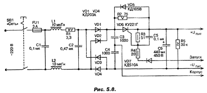
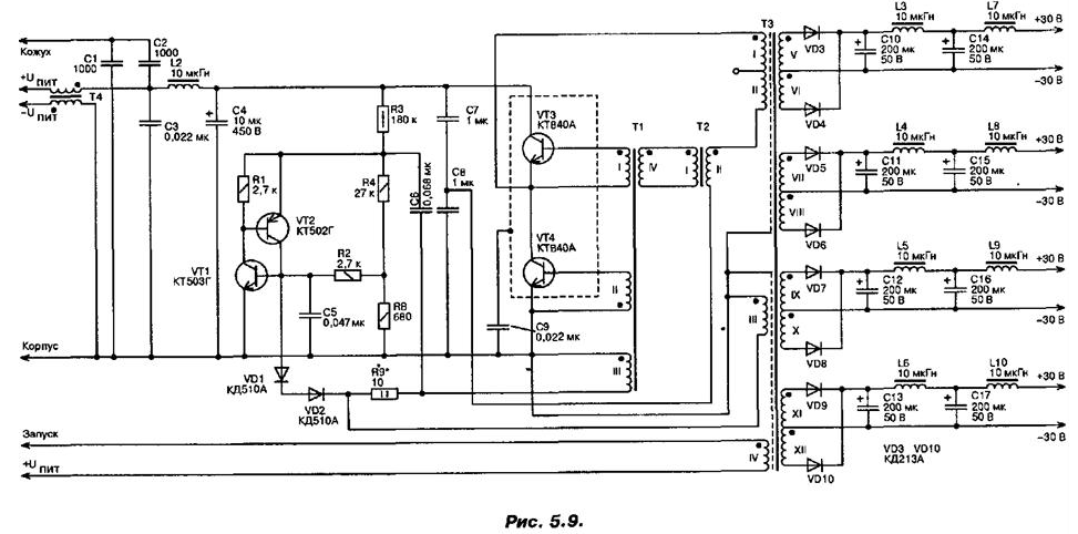
The circuit of the mains voltage rectifier is shown in Fig. 5.8, and the scheme Converter and rectifier output voltage in Fig. 5.9. Source power is not stable, since the output stage is fed. USC made by push-pull circuit and is not critical to the supply voltage.


(click to enlarge)
The main parameters of the inverter:
- nominal load power, W, not less.....200;
- the output voltage of each of the rectifiers at rated power, not less.....30;
- the output voltage of idling each of the rectifiers, not more, .....40;
- efficiency (when. P = 200 W), %, not less.....80;
- the frequency of operation of the Converter, kHz.....25...35.
To limit inrush current in the power supply mode speed increase the capacity up to par. To this end it introduced limiting resistor R2 and SCR VD6.
In the initial time SCR VD6 is closed, the charging current of the capacitor C6 limited by the resistor R2 and the inverter runs at reduced the tension. After that IV winding of the transformer. T3 on the diode VD7 comes a control voltage which opens SCR. He bypasses the resistor R2, and the Converter goes to the nominal mode of operation. Diode VD5 protects SCR VD6. Circuit R1, C2, limiting the slew rate of the voltage on the anode the SCR VD6, it eliminates accidental activation. Elements L1, L2, C3, C4 form a filter that suppresses impulse noise generated by the generator the power supply unit. Converter is a push-pull half-bridge the oscillator is triggered by a relaxation oscillator transistors VT1, VT2.
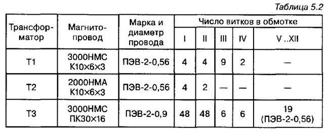
Winding data of the transformers T1...T3 are shown in table.5.2.

Recommended the procedure of winding the windings of the transformer T3 is as follows: winding I, shielding, winding V - XII, shielding, winding II, III, IV Secondary winding V - XII wound simultaneously in four wires. Transformer T4 is formed on the yoke Sh ferrite NM, each of its windings contain 40 turns of wire sew-2-0,41 All chokes - DM type. Charge Converter placed in the perforated casing. Beyond, at the output of each channel of the source power 30 In, installed: electrolytic type capacitors C50-16 capacity 1000 UF.
Author: A. P. Seman


