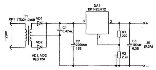
On sale is a lot of power supplies, in the form of the plug. Some of they do not have a stabilizer and for this application are not suitable for heard (pauses) network background. In a good plastic adapters the housing contains a step-down voltage transformer, rectifier, capacitors filter and regulator on the chip KREN. A typical diagram of the source supply is shown in Fig. 2.21.

Fig. 2.21. Typical scheme of a stabilized power supply
With a small quiescent current load (up to 100 mA) this source works quite well, but when it is increased the body starts to warm up much, which is explained by the fact that the work specified chips in the stabilization mode it should fall voltage is not less than 3.8 V (between input and output). At a current of 0.5 And allocated to DA1 power in the form of heat will be not less than 1.9 W. Typically this value even more due to the fact that the voltage from the secondary winding of the transformer is never selected minimum allowed because of possible instability of the mains voltage (to bring it down to 180).
The small package the adapter does not allow for good heat sink for the chip stabilizer. And, despite the fact that the heating elements of such the PSU is valid, for anybody not a secret that with the increase temperature decreases the reliability and lifetime of the source.
And if we forget this the adapter plugged in, and even at 30 degrees Celsius, pretty close to fire (thermal fuses are not all forklift power supplies).
Most audio players do not have a reliable hitchhiking at the end of the tape, and this case dramatically increases current consumption, with a long stay in this condition, for example, if you went to sleep with my Walkman on, can to damage. For example, the model of the audio player receiver with built-in WALKMAN WM-FX271 (Sony) consumes currents in modes: radio reception УSW stations - 50 mA; play with cassette - 90 mA; braked motor (at the end of the tape in the cassette) - 320 mA.
Given all the above, I decided to make a low voltage power supply, which will staying cool under all conditions of operation, to the same having a safety shutdown in case of short circuit at the output or in the case the excess current in the load preset level, for example, at the end the cassette.
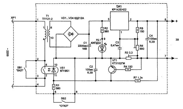
This scheme is shown in Fig. 2.22.

Fig. 2.22. Schematic diagram
To reduce the dissipation in the regulator, applied chip integral stabilizer operating at low dropout voltage (1.1 V) between the input and output CRIN (also imported from the "LOW DROP" CD, LD1085CT).
Control of BP is controlled using two buttons SB1, SB2. A momentary press SB1 supplies power to the primary winding of the transformer. In this case, due to the current through resistor R7 and diode opto-key VS1, he triggered, and the chain button SB1 is blocked. The led will HL1 recall that the source is connected to the network. In this state, the scheme will be up to the point until you press the second button SB2 or will not open the transistor VT1. To trigger the transistor it is necessary that the voltage across R3 exceeded 0.6, what happens when the output current is above the set value of this resistor value.
With proper installation, the circuit begins to work immediately and requires only the installation output voltage 2.8 to 2.9 In...by resistor R6 and through R3 - current tripping.
Adjustment of current protection operation is easier to perform when connected to the output the stabilizer of the variable resistor of about 50 Ohms (equivalent load), connected in series with the ammeter. This resistor to set the current in the load circuit, which should work protection, and tunable R3 are making off of the power source (led HL1 goes out).
When installing used parts: a setup resistors R3 SP5-VA-0.5 W; R6 - SDR-19a-0.5 W; fixed resistors MLT and S2-23; capacitors: C1 - C50-29B 16 In; C2 and C4 - C50-35 6.3 V; C3 - K10-17.
Diodes VD1...VD4 you can use any small, whose allowable forward current not less than 1 A. the Led better use of power series. MIDH.
The transistor can be used with similar conductivity of any type, but with high gain. Optocoupler key VS1 can be replaced by PT.
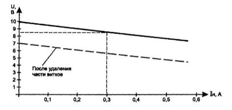
The transformer I got from the unified TP-2-6 IN and then finalized: he has a handy design (easy access for removal of excess secondary windings with winding - it can be done without disassembling the hardware). His load characteristic shown in Fig. 2.23 (shown by a dotted line characteristics after removal of about 40 turns from the secondary winding).

Fig. 2.23. The dependence of the voltage in the secondary winding of the transformer. TP-2 from the current to the load
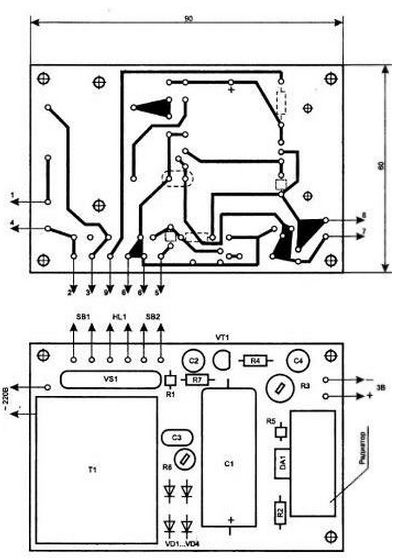
Transformer design provides for installation directly on Board. The printed circuit Board of the power source shown in Fig. 2.24. It has all details, except for the led HL1. Chip integrated stabilizer DA1 is attached to a small radiator.

Fig. 2.24. A printed circuit Board, and the arrangement of the elements
Author: I. P. Shelestov


